Dielectric constant measuring apparatus, dielectric constant measuring method, and information recording/reproducing apparatus

Inactive Publication Date: 2007-05-15
PIONEER CORP +1
View PDF49 Cites 32 Cited by
  • Summary
  • Abstract
  • Description
  • Claims
  • Application Information

AI Technical Summary

Benefits of technology

[0006]It is therefore an object of the present invention to provide a dielectric constant measuring apparatus and a dielectric constant measuring method that enable a measurement of a dielectric constant distribution in a small area of a dielectric substance and are suitable for a material evaluation of a dielectric mater

Problems solved by technology

However, there is a problem in a quantitative measurement of a dielectric constant.
However, this method could cope with onl

Method used


Image

  • Dielectric constant measuring apparatus, dielectric constant measuring method, and information recording/reproducing apparatus
  • Dielectric constant measuring apparatus, dielectric constant measuring method, and information recording/reproducing apparatus
  • Dielectric constant measuring apparatus, dielectric constant measuring method, and information recording/reproducing apparatus

Examples


first embodiment

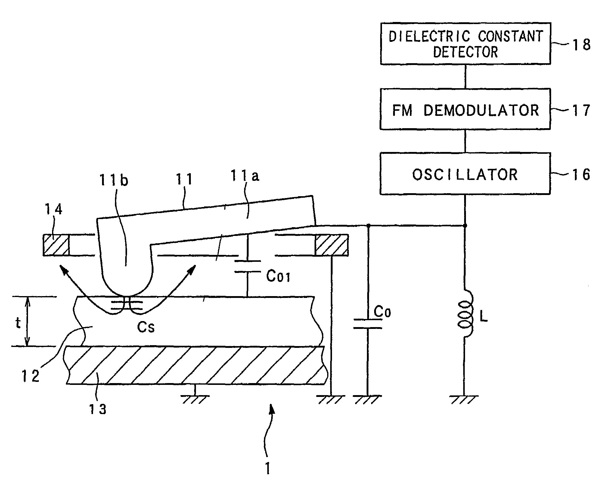
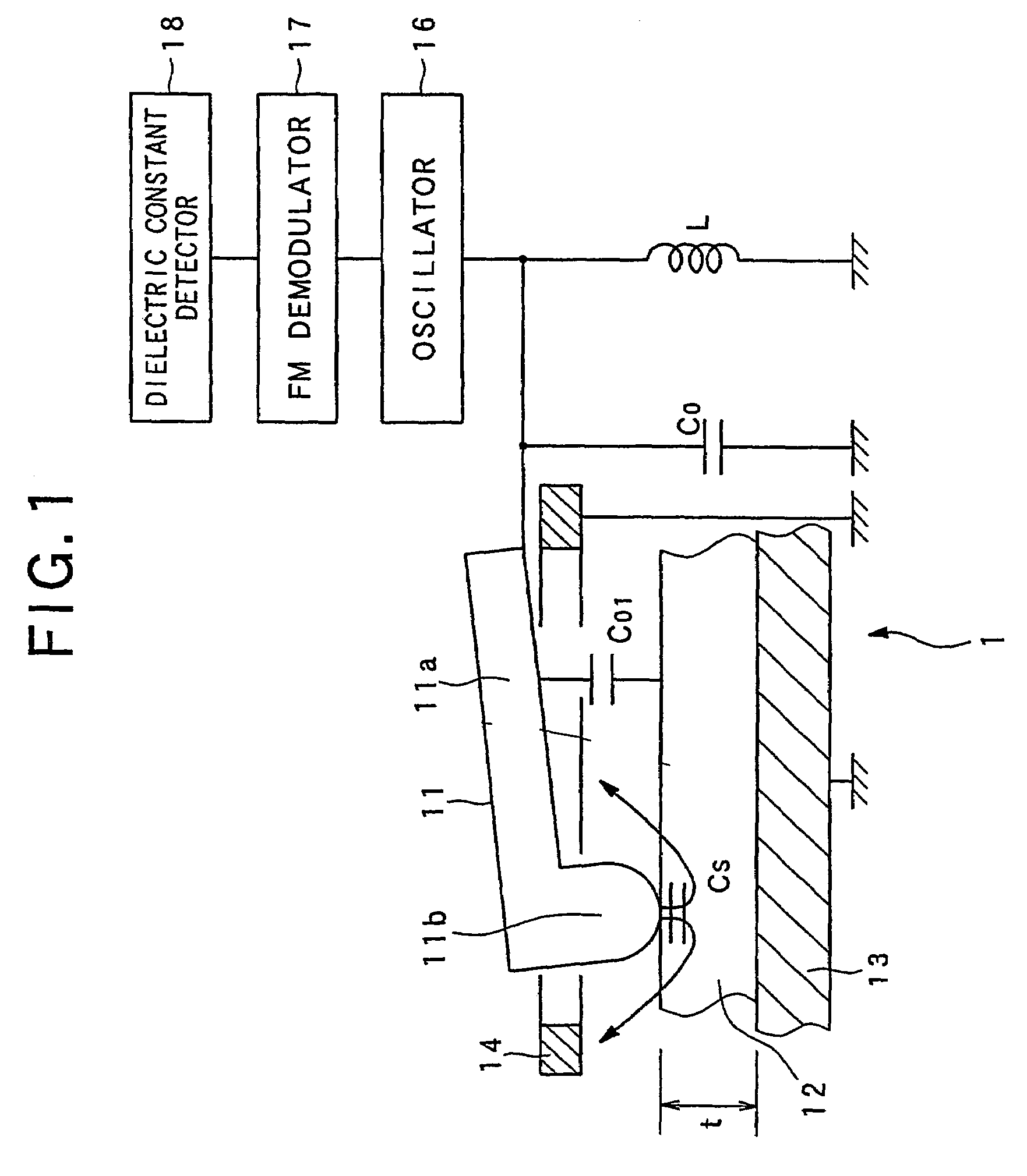
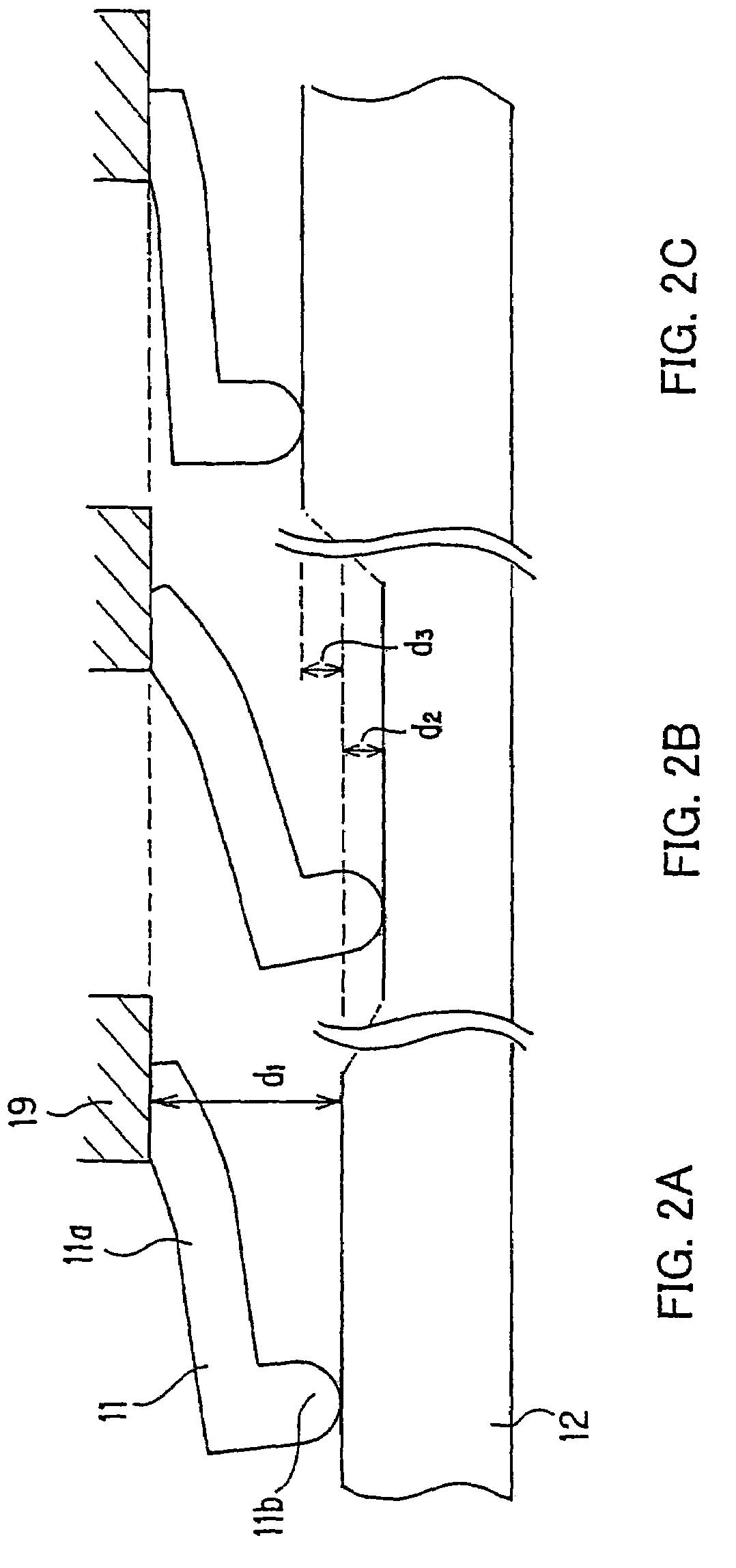
[0076]At first, a dielectric constant measuring apparatus in a first embodiment will be described below with reference to FIGS. 1 to 5. Here, FIG. 1 is a view showing the configuration of a model of a cantilever, various capacitances and a detection of a dielectric constant, FIGS. 2A to 2C are views showing a trace and a contact property with a dielectric substance of the cantilever, FIGS. 3A to 3C are views illustrating a relation between a change in a capacitance and a change in a resonance frequency, FIG. 4 is a view showing a measurement result of a standard sample of the dielectric constant change, and FIG. 5 is a view showing a working curve based on a plurality of standard samples, with regard to the change in the capacitance and the change in the resonance frequency.

[0077]As shown in FIG. 1, the configuration of a dielectric constant measuring apparatus 1 is provided with a cantilever 11, an electrode 14, an oscillator 16, an FM demodulator 17 and a dielectric constant detec...

first modification

[0108]The first modification of the first embodiment will be described below with reference to FIG. 6 and FIG. 7. FIG. 6 is a view showing the configuration of a model of a cantilever, various capacitances and a detection of a dielectric constant, and FIG. 7 is a view illustrating a relation between a polarization state of the dielectric substance and an output voltage. Also, the similar reference symbols are given to the members similar to those shown in FIG. 1, and their explanations are suitably omitted.

[0109]In the first modification, information can be reproduced or recorded, or recorded and reproduced by changing the polarization state of the small area of the dielectric substance, in the first embodiment. In particular, this is intended to be applied to the basic structure of a dielectric recording / reproducing apparatus for recording the information at a high density, by using the cantilever having the above-mentioned features as a pickup device. The actual configuration and ...

second modification

[0119]An information reproducing apparatus 2 to which the above-mentioned dielectric constant measuring technique using the cantilever is applied will be described below with reference to FIG. 8. The information is recorded in the small area of a dielectric substance at high density as the change of the polarization state of the small area. The information reproducing apparatus 2 can reproduces the recorded information by using the cantilever having the above-mentioned features as the pick-up device.

[0120]The information reproducing apparatus is provided with a dielectric substance recording medium 21 composed of a dielectric substance 22 and a substrate 23, a cantilever 24, an electrode 25, an alternating current signal generator 26, an oscillator 27, an FM demodulator 28, a signal detector 29, an inductor L, an inductor La and a capacitance Ca. Here, the above-mentioned floating capacitance and the like are assumed to be determined by using a predetermined manner, and they are not...


PUM


Abstract

A dielectric constant measuring apparatus for measuring a dielectric constant of a dielectric substance is provided with: a cantilever having a small projection on a tip side of a cantilevered electric conductor; an electrode which is placed around the cantilever and is earthed; an inductor (L) placed so as to constitute a resonance circuit together with a capacitance (Cs) in a small area of the dielectric substance that the cantilever contacts; an oscillating device connected to the resonance circuit; a demodulating device for demodulating an oscillation frequency of the oscillating device; and a dielectric constant detecting device for detecting a dielectric constant information from a demodulation signal of the demodulating. The dielectric constant measuring apparatus can be applied to an information recording/reproducing apparatus using a dielectric record medium.

Description

[0001]This application is the U.S. national phase of international application PCT / JP02 / 09223, filed in English on 10 Sep. 2002, which designated the U.S. PCT / JP02 / 09223 claims priority to JP Application No. 2001-274347, filed 10 Sep. 2001. The entire contents of these applications are incorporated herein by reference.TECHNICAL FIELD[0002]The present invention relates to a dielectric constant measuring apparatus and a dielectric constant measuring method which measure a dielectric constant of a small area of a dielectric substance, and an information recording / reproducing apparatus to which this dielectric constant measuring technique is applied.BACKGROUND ART[0003]In recent years, many kinds of ferroelectric materials and piezoelectric materials have been developed and used for a supersonic, an optical device and a memory and the like. In association with it, a development of methods of measuring a residual polarization distribution of the ferroelectric material and a local anisotr...

Claims


Application Information

Patent Timeline
IPC IPC(8): G11B7/00G01Q40/02G01Q60/00G01Q60/24G01Q60/46G01Q80/00G01R27/26
CPCG01R27/2635G01R27/2676
Inventor CHO, YASUOONOE, ATSUSHI
Owner PIONEER CORP
Why Eureka
Try Eureka