Thin film ultrasonic transmitter/receiver

a transmitter and ultrasonic technology, applied in the field of thin film ultrasonic transmitters and receivers, can solve the problems of difficult manufacturing of transducers, limited application of pvdf to transmit ultrasonic transducers, and difficult effort to provide highly repeatable measurements. , to achieve the effect of increasing acoustic output, simplifying manufacturing process, and being suitable for us

Active Publication Date: 2007-05-29
GENERAL ELECTRIC CO
View PDF9 Cites 12 Cited by
  • Summary
  • Abstract
  • Description
  • Claims
  • Application Information

AI Technical Summary

Benefits of technology

[0006]The present invention provides an ultrasonic transmitter and receiver using a piezoelectric film and suitable for use in ultrasonic imaging systems. The transducer provides suitable output levels and may operate in a non-resonant mode avoiding some of the difficulties of manufacturing present ceramic transducers. The non-resonant mode also allows rapid sequential transmission and reception of ultrasonic signals from local targets (for example, in medical imaging) without interference from transducer ringing.
[0007]Generally, the invention employs a set of thin metallic backer electrodes attached to the piezoelectric film that provides a sharp discontinuity in acoustic impedance at the back surface of the piezoelectric film to increase the acoustic output from the piezoelectric film's front surface during transmission. During reception, each of the backer electrodes operates independently to provide spatial discrimination necessary for most quantitative applications. During transmission, the backer electrodes operate in unison, for example, as a ground plane. The metallic backer electrodes may be copper adhered to a printed circuit board further simplifying the manufacturing process.

Problems solved by technology

Operation in this “resonant” mode increases the output of the transducer, but can make manufacturing of the transducer difficult because of the high sensitivity of the transducers resonant frequency to variations in the dimensions of the many subcomponents of the transducer.
Slight differences in resonant frequencies of the transducers on different machines complicate the effort to provide highly repeatable measurements that are machine independent.
Application of PVDF to transmitting ultrasonic transducers has been limited because of low output levels.

Method used


Image

  • Thin film ultrasonic transmitter/receiver
  • Thin film ultrasonic transmitter/receiver

Examples


Embodiment Construction

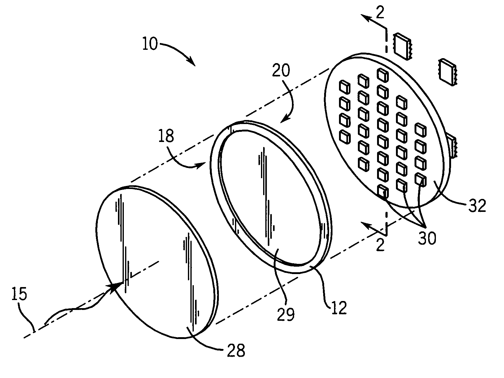
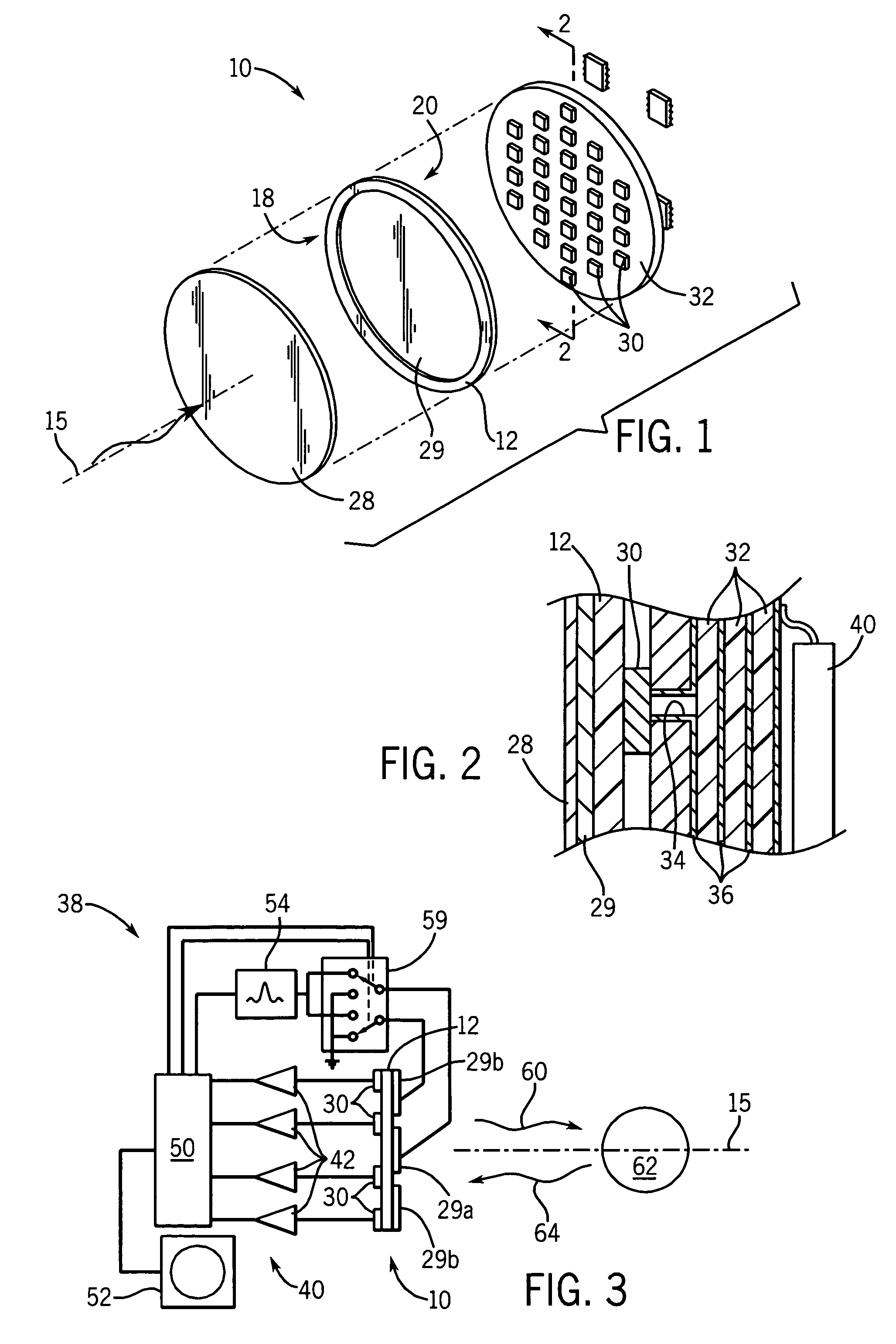
[0011]Referring now to FIG. 1, an ultrasonic transmitting and receiving transducer 10 constructed according to the present invention includes a disk-shaped piezoelectric film 12. In the preferred embodiment, the piezoelectric film 12 may be a polyvinylidene fluoride film (PVDF) that has been polarized to create piezoelectric properties according to methods well understood in the art.

[0012]A front face 18 of the piezoelectric film 12 is preferably coated with a thin flexible layer of conductive material such as copper. This front electrode 29 may be coated with nickel to reduce corrosion. These materials may be applied by vacuum metallization or electroplating or other methods and creates a front electrode 29 which is continuous. The electrode may also be sub-divided into multiple elements such as to allow individual stimulus to various parts of the assembly. Devices organized in this manner would be capable of generating a focused or otherwise directed sound beam.

[0013]The front fac...


PUM

PropertyMeasurementUnit
thicknessaaaaaaaaaa
thickaaaaaaaaaa
thickaaaaaaaaaa

Abstract

A thin film piezoelectric material employs an array of metallic backer plates to provide high output, non-resonant ultrasonic transmission and reception suitable for ultrasonic measurement and / or imaging.

Description

CROSS-REFERENCE TO RELATED APPLICATIONS[0001]This application is a continuation-in-part of U.S. patent application Ser. No. 10 / 713,417 filed Nov. 14, 2003, hereby incorporated by reference.BACKGROUND OF THE INVENTION[0002]The present invention relates to ultrasonic acoustic combination receivers and transmitters, such as may be used in quantitative ultrasonic imaging and measurements, and in particular to an improved thin film receiver / transmitter.[0003]Quantitative ultrasonic imaging is used, for example, in bone densitometry where ultrasound is transmitted through in vivo bone, most typically the os calcis of the heel, in order to measure trabecular bone. Common measurements made by such densitometers include the speed of sound (SOS) and broadband ultrasonic attenuation (BUA) in the bone. Images of the bone based on these or other measurements may also be provided by the densitometer. Densitometers of this type are described in U.S. Pat. Nos. 5,840,029 and 6,517,487, assigned to t...

Claims


Application Information

Patent Timeline
Patent Type & Authority Patents(United States)
IPC IPC(8): A61B8/00G01N9/24G01N29/06G01N29/24
CPCG01N29/06G01N29/245
Inventor MORRIS, RICHARD FRANKLINMORRIS, STEVEN TAYLOR
Owner GENERAL ELECTRIC CO
Why Eureka
Try Eureka