
Low NOx combustion

Active Publication Date: 2007-06-05
PRAXAIR TECH INC
View PDF93 Cites 13 Cited by
  • Summary
  • Abstract
  • Description
  • Claims
  • Application Information

AI Technical Summary

Benefits of technology

[0022]One aspect of the present invention, which can also be considered a method for retrofitting existing combustion devices, is a method that reduces the amount of NOx emitted comprising:
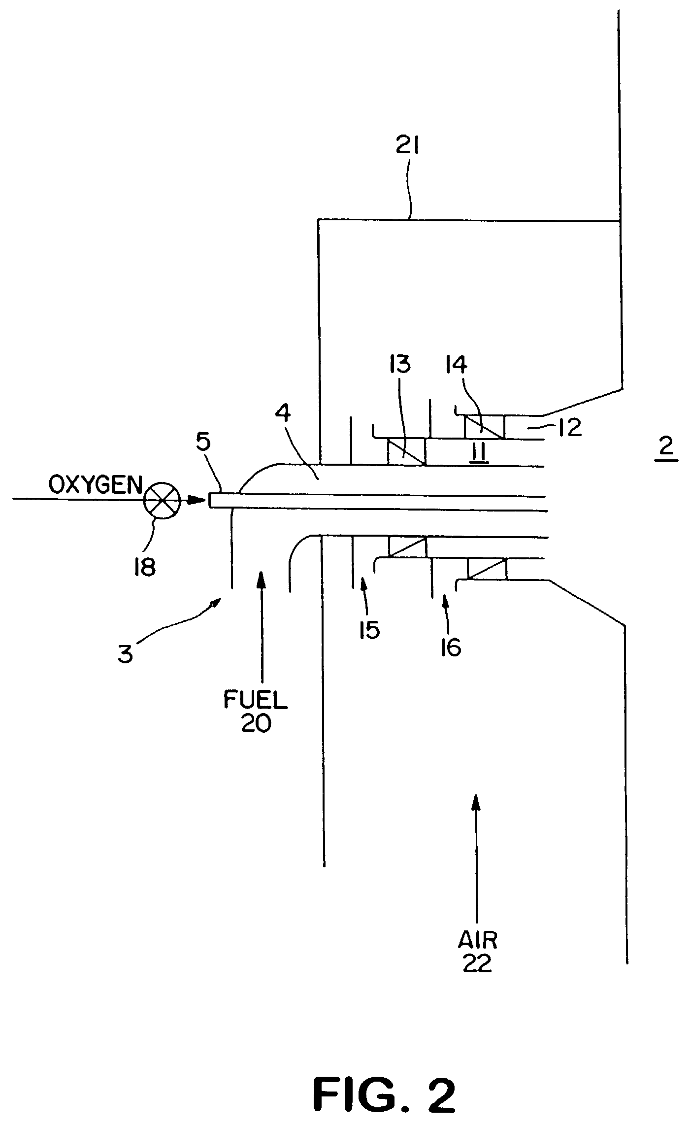
[0032]feeding oxygen into said fuel by injecting it directly into said fuel in said fuel-rich zone as said fuel emerges from said burner or by adding it to the air that is fed through said burner, so that the oxygen combusts with said fuel in said fuel-rich zone, in an amount of said oxygen which is less than 20% or even than 25% of the stoichiometric amount required for complete combustion of said fuel, and adjusting the amount of air fed through said burner so that the stoichiometric ratio in said fuel rich zone is between 0.1 and 0.85, while maintaining or enlarging the size of said fuel-rich zone compared to its size when combustion is carried out in said combustion device without said oxygen feeding step but under otherwise identical conditions.

Problems solved by technology

Since sufficient air velocities must be provided to mix fuel and air within the furnace space to complete combustion, it is difficult to create a very large fuel rich zone to provide a long enough residence time for maximum NOx reduction.
Although the LNB is a fairly inexpensive way to reduce NOx and many advancements have been made in the burner design, currently available versions are not yet capable to reach the emissions limits in pending regulations of 0.15 lb (as NO2) per MMBtu of coal fired for utility boilers.
These tests were single particle combustion tests performed under highly fuel lean conditions, which does not provide information on how much oxygen is needed to accomplish this under more realistic combustion conditions.
Although the prior art describes several elegant enhancements for staged combustion and LNB's, several practical problems have limited their application.
First, preheating the combustion air to the levels required to enhance the kinetics requires several modifications to both the system and the air piping.
All of the modifications can be costly and can have a negative impact on the operation of the boiler.
The primary barrier to the use of oxy-fuel firing in boilers has been the cost of oxygen.
However, for more efficient operations, such as boilers, the fuel savings attainable by using oxy-fuel firing is typically much lower than the cost of oxygen.
Clearly, this is uneconomic for most boilers.

Method used


Image

  • Low NOx combustion
  • Low NOx combustion
  • Low NOx combustion

Examples


example 1

[0090]Oxygen was mixed into the combustion air supplied to the first stage of a 17 kW thermal self-sustained downfired experimental furnace with 6″ internal diameter. The oxygen enriched combustion air was fed to a premixed non-swirled pulverized coal-air burner. High volatile A bituminous coal (Illinois No.6) was used. Oxygen was fed at a rate to replace 20% by volume of the combustion air, on an oxygen equivalent basis, supplied to the primary combustion zone (PCZ). This was equivalent to 10 to 20% of the stoichiometric air requirement. “Over fire air” was injected into the furnace approximately eight feet downstream of the burner face, which provided gas residence time of about 1 second in the PCZ. Sufficient over fire air was injected to keep the overall stoichiometric ratio at approximately 1.2. Although the temperature at the over fire air injection point varied according to the primary combustion zone stoichiometric ratio, it was held as constant between the air (baseline) an...

example 2

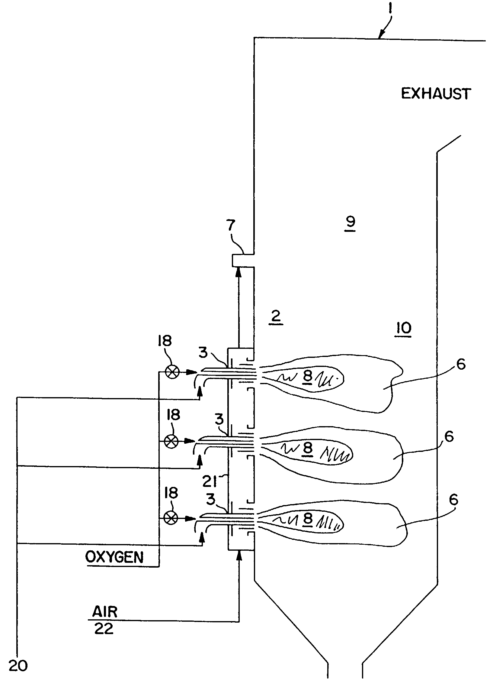
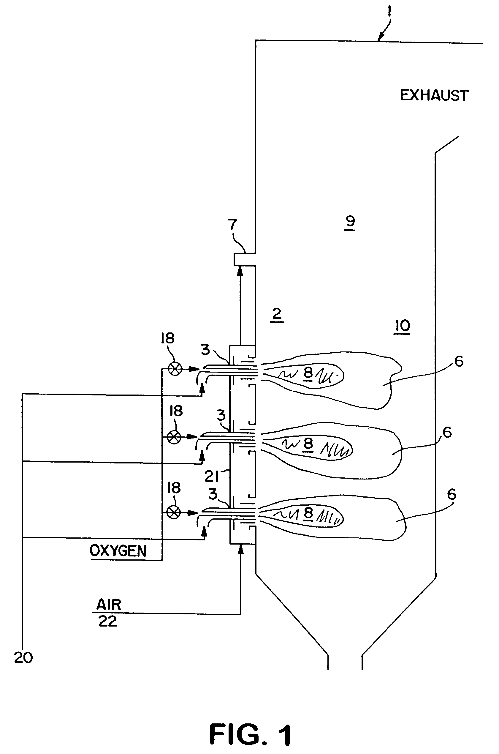
[0091]A low NOx coal-air burner was fired at about 4 MMBtu / hr in a refractory lined test furnace with internal dimensions of about 3.6 ft wide×3.6 ft high and 41 ft long. A pair of over fire air ports were located at about 10.5 ft from the burner exit. The burner is similar to one shown in FIG. 2 and consists of a central round passage and several annular passages for coal, air, oxygen and natural gas streams. The central passage was either used to insert an 1.9″ OD and 1.5″ ID oxygen lance or blocked to provide a bluff body to enhance gas recirculation for flame stability. Coal and primary air were injected from the first annular passage of 3.068″ OD and 1.9″ ID. The second annular passage (4.026″ OD and 3.5″ ID) was used to inject either natural gas or oxygen. The third (6.065″ OD and 4.5″ ID) and the fourth (7.981″ OD and 6.625″ ID) annular passages were used for secondary and tertiary air flows and were equipped with variable swirl generators to impart swirling flows. The burner...

example 3

[0098]A commercial low NOx coal-air burner, the RSFC™ burner described in U.S. Pat. No. 5,960,724, was fired at about 24 MMBtu / hr in a refractory lined test furnace with internal dimensions of about 7.5 ft wide×7.5 high and 34 ft long. One or two opposed pairs of over fire air ports were located at about 26 feet from the burner exit. The burner consists of a central round passage and several annular passages for coal, air, oxygen streams. The central passage was used to insert an 1.9″ OD and 1.5″ ID oxygen lance. Coal and primary air were injected from the first annular passage. The second, third and the fourth annular passages were used for secondary, tertiary, and quaternary air flows and were equipped with variable swirl generators to impart swirling flows. The burner is designed to provide an aerodynamically staged combustion condition. A relatively large fuel rich combustion zone is created along the axis of the burner with relatively gradual mixing of tertiary and quaternary a...


PUM


Abstract

Combustion of hydrocarbon liquids and solids is achieved with less formation of NOx by feeding a small amount of oxygen into the fuel stream.

Description

[0001]This application claims priority from U.S. Provisional Application Ser. No. 60 / 380,818 filed May 15, 2002.[0002]This invention was made with United States Government support under Cooperative Agreement No. DE-FC26-00NT40756 awarded by the Department of Energy. The United States Government has certain rights in the invention.FIELD OF THE INVENTION[0003]The present invention relates to combustion of hydrocarbon fuels containing bound nitrogen, particularly of coal.BACKGROUND OF THE INVENTION[0004]Environmental awareness is growing in the U.S. and around the world leading to increasing public and regulatory pressures to reduce pollutant emissions from boilers, incinerators, and furnaces. One pollutant of particular concern is NOx (by which is meant oxides of nitrogen such as but not limited to NO, NO2, NO3, N2O, N2O3, N2O4, N3O4, and mixtures thereof), which has been implicated in acid rain, ground level ozone, and) particulate formation.[0005]A number of technologies are availab...

Claims


Application Information

Patent Timeline
IPC IPC(8): F23J15/00F23L9/00F23C5/32F23C6/04F23D1/02F23L7/00
CPCF23C5/32F23C6/045F23D1/02F23L7/007F23C2201/101F23C2201/20Y02E20/344F23C2900/99004F23D2900/00006F23C2900/07021Y02E20/34
Inventor KOBAYASHIBOOL, III, LAWRENCE E.
Owner PRAXAIR TECH INC
Learn More