Cellular radio communication system with frequency reuse

Active Publication Date: 2007-06-05
TELEFON AB LM ERICSSON (PUBL)
View PDF14 Cites 29 Cited by
  • Summary
  • Abstract
  • Description
  • Claims
  • Application Information

AI Technical Summary

Benefits of technology

[0013]Soft or diversity handover is readily supported in CDMA systems where the frequency reuse is one. Soft handover is typically used in a CDMA system with an uplink a frequency reuse of one, in order to avoid excessive uplink interference and significant capacity loss. In soft handover, an uplink transmission from a mobile station is received by multiple neighbor base stations, e.g., base stations in a so-called “active set.” In addition, all base stations in the active set transmit on the downlink to the mobile station. Each of the power control commands transmitted from all base stations in the active set is considered by the mobile station when it regulates its uplink transmit power. Mobile uplink transmissions are usually simultaneously power controlled from all base stations in the active set in such a way that if any of the base stations requests a reduction in power, the mobile terminal transmit power is reduced. The mobile terminal transmit power is only increased if all base stations in the active set request an increa

Problems solved by technology

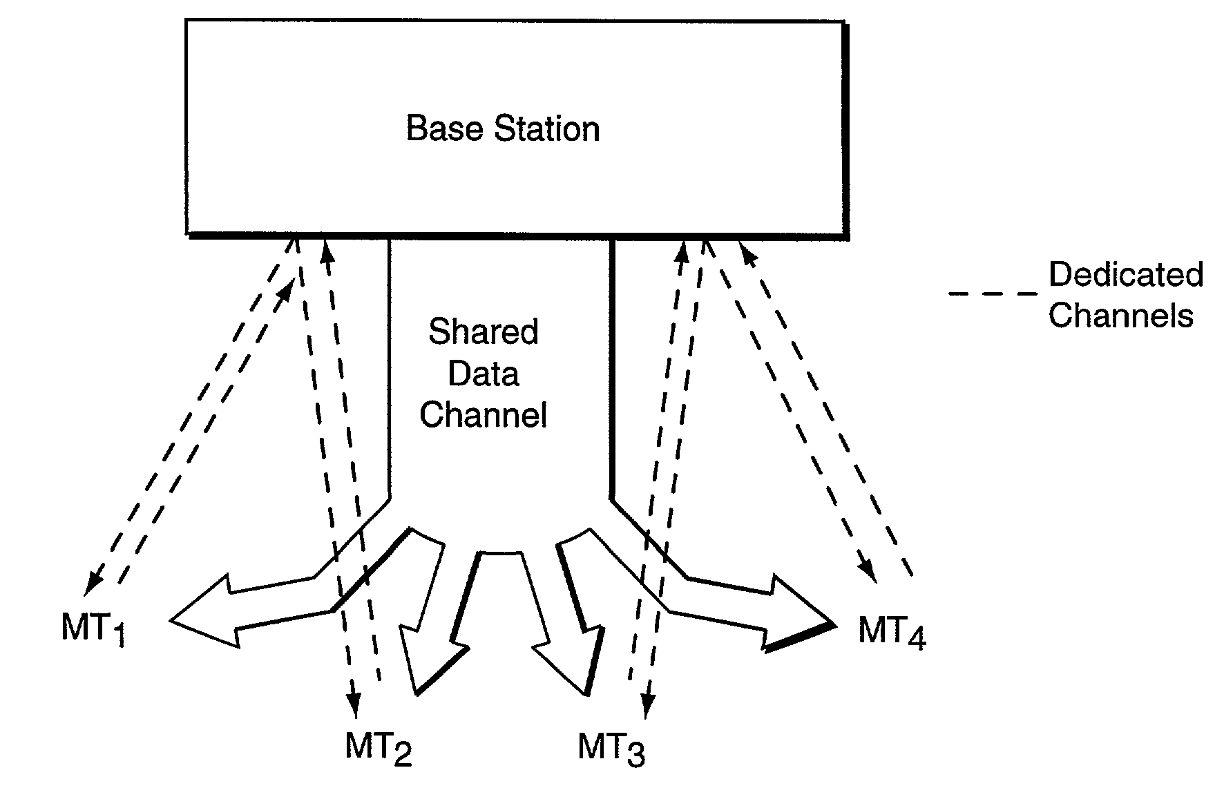
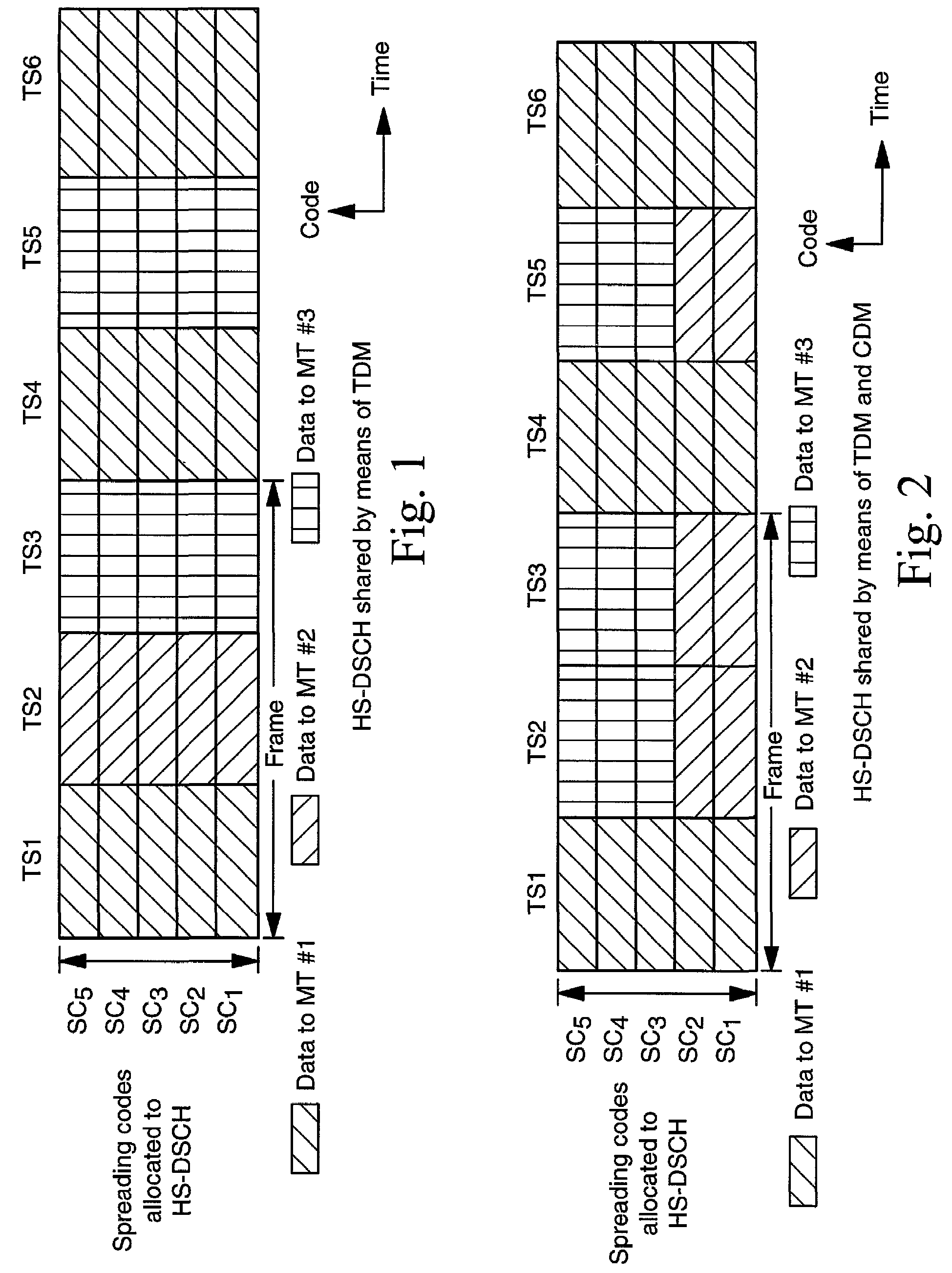
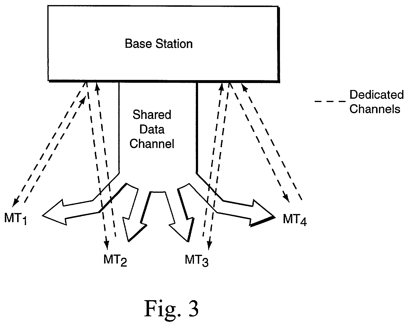
One issue regarding such a high speed downlink shared channel is how to offer satisfactory quality of service to all mobile terminals in the cell.
The problem with a frequency reuse of one is the high level of inter-cell interference, i.e., interference originating from neighbor cells.
Larger variations in channel quality may result from higher levels of downlink interference that may be present in the cell, especially close to the cell border.
Although there is a benefit in terms of lower inter-cell interference, and thus improved services for mobiles at cell borders achieved by employing a frequency reuse

Method used


Image

  • Cellular radio communication system with frequency reuse
  • Cellular radio communication system with frequency reuse
  • Cellular radio communication system with frequency reuse

Examples


Embodiment Construction

[0030]In the following description, for purposes of explanation and not limitation, specific details are set forth, such as particular embodiments, procedures, techniques, etc., in order to provide a thorough understanding of the present invention. However, it will be apparent to one skilled in the art that the present invention may be practiced in other embodiments that depart from these specific details. In some instances, detailed descriptions of well-known methods, interfaces, devices and signaling techniques are omitted so as not to obscure the description of the present invention with unnecessary detail. Moreover, individual function blocks are shown in some of the figures. Those skilled in the art will appreciate that the functions may be implemented using individual hardware circuits, using software functioning in conjunction with a suitably programmed digital microprocessor or general purpose computer, using an Application Specific Integrated Circuit (ASIC), and / or using a ...


PUM


Abstract

Different frequency reuse values are associated with different channels, e.g., different types of channels in a cellular communications system. For a high speed downlink shared type of channel, the frequency reuse may be greater than one in order to achieve higher data rates. On the other hand, the frequency reuse may be set to one for other channel types, e.g., dedicated channels including both uplink and downlink dedicated channels. Alternatively, the frequency reuse may also be set greater than one for channels in addition to the downlink shared channel, e.g., one or more dedicated downlink channels, while a frequency reuse of one is deployed for one or more uplink dedicated channels. Using different frequency reuse values reduces inter-cell interference, particularly at cell borders, while still maintaining existing soft handover schemes for dedicated channels if one or more of the channels is a code division multiple access (CDMA) type of channel.

Description

FIELD OF THE INVENTION[0001]The present invention relates to radio communications, and more particularly, to enhancing flexibility and services of a Code Division Multiple Access radio communication system.BACKGROUND AND SUMMARY OF THE INVENTION[0002]In order to increase the capacity of a cellular radio communications network, different access strategies may be employed. Rather than assigning a particular frequency bandwidth to a single radio communication as in Frequency Division Multiple Access (FDMA)-based systems, time division multiplexing may be employed as in Time Division Multiple Access (TDMA)-based systems to increase the number of user communications that use the same frequency bandwidth. Multiple users transmit on the same frequency bandwidth, but at a different time. In Code Division Multiple Access (CDMA), multiple users share the same frequency bandwidth, but each radio communication is assigned a different spreading code used by a receiver to extract the desired info...

Claims


Application Information

Patent Timeline
IPC IPC(8): H04Q7/00H04B7/216H04J1/00H04Q7/20H04B7/26H04W16/02H04W16/12H04W36/18H04W72/12
CPCH04B7/2618H04L5/0032H04L5/0073H04W16/12H04L5/0021H04W36/18
Inventor DAHLMAN, ERIKPARKVALL, STEFAN
Owner TELEFON AB LM ERICSSON (PUBL)
Why Eureka
Try Eureka