Bi-level iso-surface compression

a compression and isosurface technology, applied in the field of computer graphics and scientific visualization, can solve the problems of large increase in the cost per vertex, major bottleneck in transmission time, and incompatible with the out-of-core nature of all these approaches, and achieve the effect of improving the quality of the reconstructed polygon mesh

Inactive Publication Date: 2007-06-12
ACTIVISION PUBLISHING
View PDF14 Cites 98 Cited by
  • Summary
  • Abstract
  • Description
  • Claims
  • Application Information

AI Technical Summary

Benefits of technology

[0031]Thus, this invention provides methods, apparatus and systems for a new and simple algorithm to compress isosurface data. This is the data extracted by isosurface algorithms from scalar functions defined on volume grids, and used to generate polygon meshes or alternative representations. Isosurfaces are in widespread use in medical imaging, and scientific computation. The main features of this invention are its extreme simplicity and high compression ratios, which are 5 to 25 times better than those obtained with general purpose mesh compression schemes.
[0033]An in-core isosurface decoder process produces a polygon mesh as a surface representation. This decoder process takes as input a compressed isosurface data with neither the optional intersection points record nor the normal vectors record. In this decoder the normalized intersection points are set to the default value one half, the normal vectors are given default values as a function of the neighboring intersection point values. A subsequent smoothing algorithm is used as a global predictor to improve the quality of the reconstructed polygon mesh.

Problems solved by technology

When the geometry information (vertex coordinates, and optionally normals, colors, and texture coordinates) is also taken into account, the cost per vertex increases considerably.
In addition, all of these approaches are incompatible with the out-of-core nature of isosurface extraction algorithms that visit the voxels in scan order.
In both cases the transmission time constitutes a major bottleneck because of the large file sizes involved.
In the first case, in addition to the size of the transmitted data, the burden of the computation is shifted to the client.
For binary data, where the alphabet is composed of two symbols, keeping track of global symbol frequencies is usually not good enough as a model update procedure, and a “context-based” procedure is used.

Method used


Image

  • Bi-level iso-surface compression
  • Bi-level iso-surface compression
  • Bi-level iso-surface compression

Examples


embodiment 1200

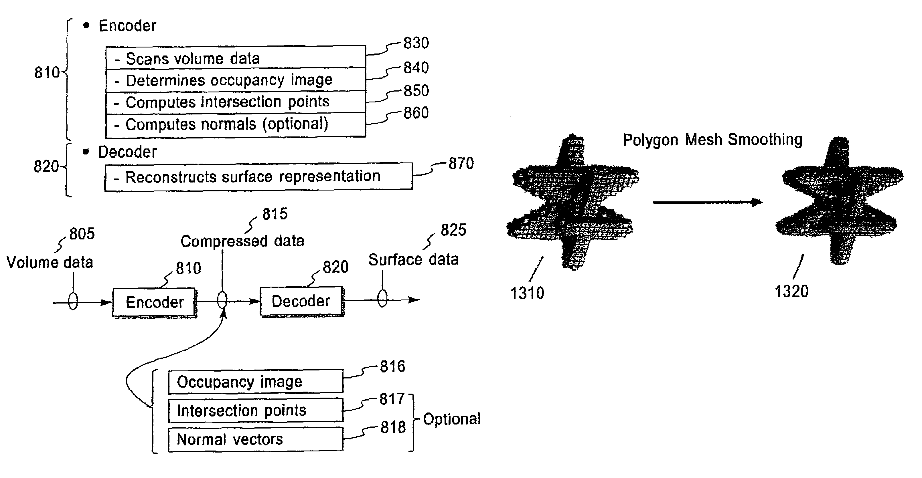
[0061]FIG. 12 is a flow chart showing the steps of an example of an advantageous embodiment 1200 of the isosurface decoder process 820 of FIG. 8. This advantageous embodiment can decode the compressed isosurface data 815 produced by the isosurface encoder process 810 with or without the optional records 817 and 818. While scanning the volume data in scan order, the method decodes the occupancy image, the intersection points, and the intersection point surface normals. This embodiment can produce either a polygon mesh or a set of oriented points as output surface representation. If producing a polygon mesh as output surface representation, from the information included in the occupancy image the method generates in step 1230 the topology and connectivity of the reconstructed polygon mesh. If producing a set of oriented points as output surface representation, step 1230 is not performed. From the location of the intersection points and the intersection point normals, the method recons...

embodiment 1400

[0063]FIG. 14 is a flow chart of an in-core more advantageous embodiment 1400 of the isosurface decoder process of FIG. 12, which produces a polygon mesh as a surface representation. This advantageous implementation takes as input a compressed isosurface data 815 with neither the optional intersection points record 817 nor the normal vectors record 818. In this embodiment step 1410 replaces step 1250 of the flow chart 1200. In step 1410 the normalized intersection point parameter is set to the default value one half. In step 1420 the normal vector corresponding to the intersection point is given a default value as a function of the neighboring intersection point values. In this advantageous embodiment the smoothing step 1297 is mandatory to improve the quality of the reconstructed polygon mesh.

embodiment 1500

[0064]FIG. 15 is a flow chart of an out-of-core more advantageous embodiment 1500 of the isosurface decoder process of FIG. 12, which produces a set of oriented points as a surface representation. This advantageous implementation takes as input a compressed isosurface data 815 with the optional intersection points record 817 and the normal vectors record 818. After step 1260 this advantageous embodiment has the additional step 1510 of generating one oriented point. The output surface representation is the set of oriented points generated in step 1510.

[0065]Thus the present invention includes a data structure comprising, a memory of a computer system storing the data structure for representing an isosurface polygonal mesh, the isosurface polygonal mesh approximating a level set of a scalar function, the scalar function defined by function values and a regular three-dimensional grid, the level set defined by an isolevel, each function value associated with a node of the regular three-...


PUM


Abstract

Methods, structures and systems for encoding and decoding isosurface data. An encoder process takes volume data and an isolevel as input and produces compressed isosurface data as output. The compressed isosurface data produced by an encoder process is composed of an occupancy image record, an optional intersection points record, and an optional normal vectors record. An occupancy image is compressed with a context-based arithmetic encoder. Compressed isosurface data can be stored in a data storage device or transmitted through a communication medium to a remote computer system, where the decoder process is executed. The decoder processes take compressed surface data as input and produce surface data as output. The decoder processes first reconstructs the occupancy image by decoding the occupancy image record. An in-core isosurface decoder process produces a polygon mesh as a surface representation. An out-of-core isosurface decoder process produces a set of oriented points as a surface representation.

Description

PRIORITY[0001]This application claims priority to a Provisional Application, having the same title, assigned, Ser. No. 60 / 400,202, and filed Jul. 31, 2002, which is incorporated herein by reference in its entirety for all purposes.FIELD OF THE INVENTION[0002]This invention relates to the fields of computer graphics and scientific visualization. It is more particularly related to representing isosurface data in compressed form, especially suitable for compact storage and fast transmission, and remote visualization.BACKGROUND OF THE INVENTION[0003]Polygon meshes are widely used in computer aided geometric design, geometric modeling, medical imaging, and computer graphics to represent surfaces in digital form. Polygon meshes are described in detail in U.S. Pat. No. 5,506,947 “Curve and Surface Smoothing Without Shrinkage,” by G. Taubin, and in the paper “A Signal Processing Approach To Fair Surface Design,” by G. Taubin, Siggraph'95 Conference Proceedings, August 1995, pages 351-358, b...

Claims


Application Information

Patent Timeline
Patent Type & Authority Patents(United States)
IPC IPC(8): G06T17/00G06T15/00G06T15/10G06K9/36G06K9/46G06T9/00
CPCG06T9/00
Inventor TAUBIN, GABRIEL
Owner ACTIVISION PUBLISHING
Why Eureka
Try Eureka