

Assessment of lesion transmurality
a transmurality and lesion technology, applied in the field of surgical instruments for laser cardiac ablation procedures, can solve the problems of reducing physical activity, stroke, atrial fibrillation, and particularly difficult, and achieve the effect of improving visualization of the ablation procedur
- Summary
- Abstract
- Description
- Claims
- Application Information
AI Technical Summary
Benefits of technology
Problems solved by technology
Method used
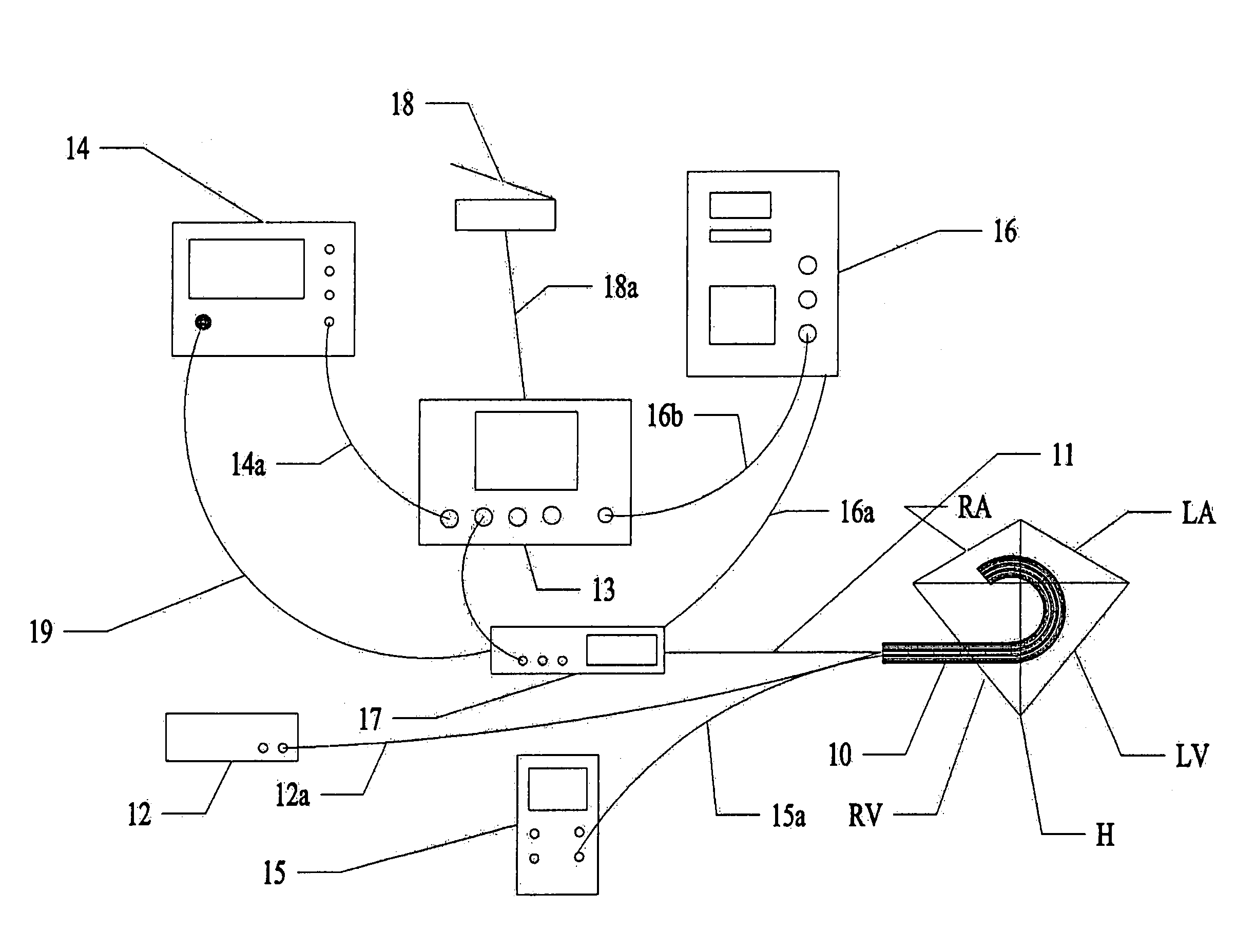
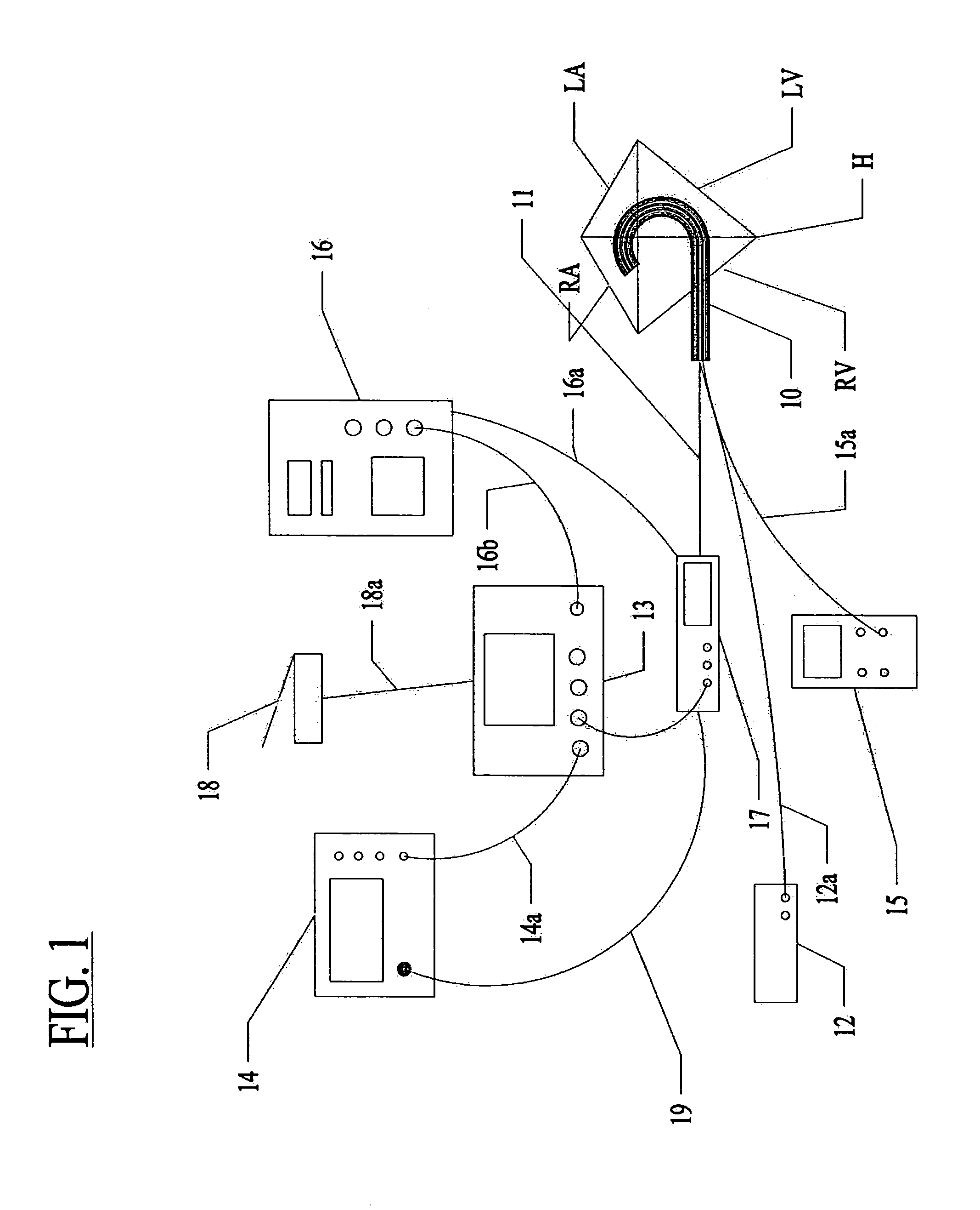
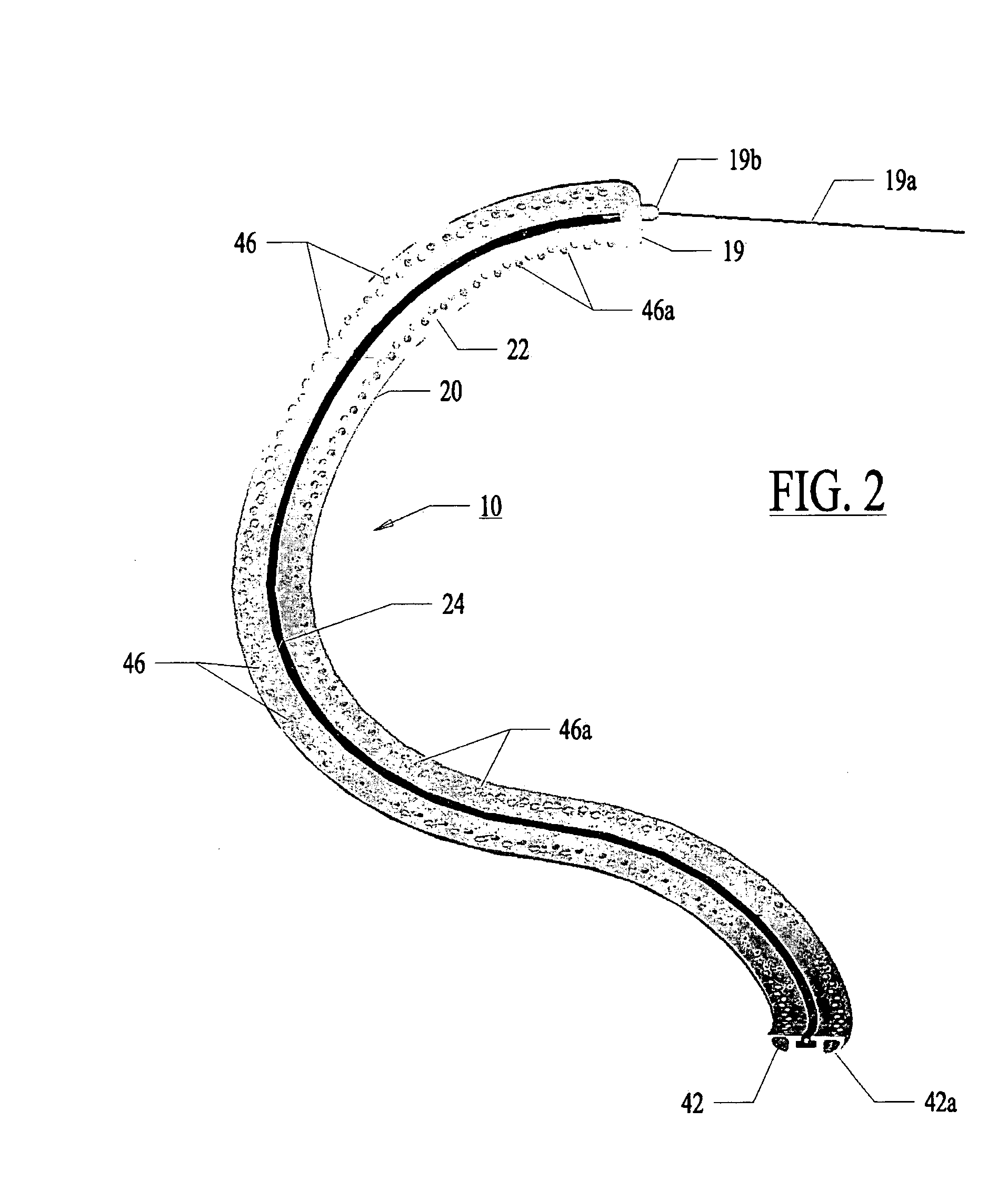
Image

Examples
embodiment
Multi-Fiber Embodiment
[0154]In a most preferred embodiment, the optical fiber 32 with the fluid conduit 30 is pushed and pulled with the fiber's longitudinal axis generally aligned with the axis X-X of the control guide member. The fiber 32 is side-firing fiber as illustrated in FIG. 7. Light is emitted from the fiber perpendicular to the axis of the fiber 32 at the fiber tip 33. The fiber is not bent or radiused.
[0155]FIG. 21 illustrates an alternative to a side-firing fiber 32. In FIG. 21, multiple fibers 321 can be placed within a common channel 301 which can be linearly drawn through the guide member 20.
[0156]With use of very small fibers 321 (50-micron fibers), the individual fibers 321 can be bent such that the fibers 321 are not side firing. Instead, the fibers 321 emit light out of a distal tip 331 in a direction parallel to the fiber axis at the distal tip 331.
[0157]The channel 301 is microporous plastic transparent to the therapeutic wavelength. Micro pores 351 opposing th...
PUM
 Abstract
Description
Claims
Application Information