Polarizing optical element and display device including the same

a technology of optical elements and display devices, applied in the direction of polarising elements, instruments, record information storage, etc., can solve the problems of low optical efficiency, decrease in contrast on the screen, increase in the number of required components and manufacturing costs, and achieve excellent optical efficiency and high contrast ratio

Inactive Publication Date: 2007-06-19
SHARP KK
View PDF8 Cites 46 Cited by
  • Summary
  • Abstract
  • Description
  • Claims
  • Application Information

AI Technical Summary

Benefits of technology

[0008]In order to overcome the problems described above, preferred embodiments of the present invention provide a polarizing optical element, which is thin, ensures excellent optical efficiency, and achieves a high contrast ratio even when applied to a display device by itself.
[0022]Various preferred embodiments of the present invention described above provide a polarizing optical element, which is thin and ensures excellent optical efficiency. Thus, by applying a polarizing optical element according to a preferred embodiment of the present invention to a display device, a high-contrast image can be displayed.

Problems solved by technology

However, if such an absorbing polarizer is used in a display device, then the transmittance to natural light can never exceed 50% in principle, thus resulting in low optical efficiency.
However, if this polarizer is used by itself in a display device, dark display is not realized due to low light attenuation and therefore the contrast decreases on the screen.
In that case, however, the number of required components and the manufacturing cost both increase.

Method used


Image

  • Polarizing optical element and display device including the same
  • Polarizing optical element and display device including the same
  • Polarizing optical element and display device including the same

Examples


embodiment 1

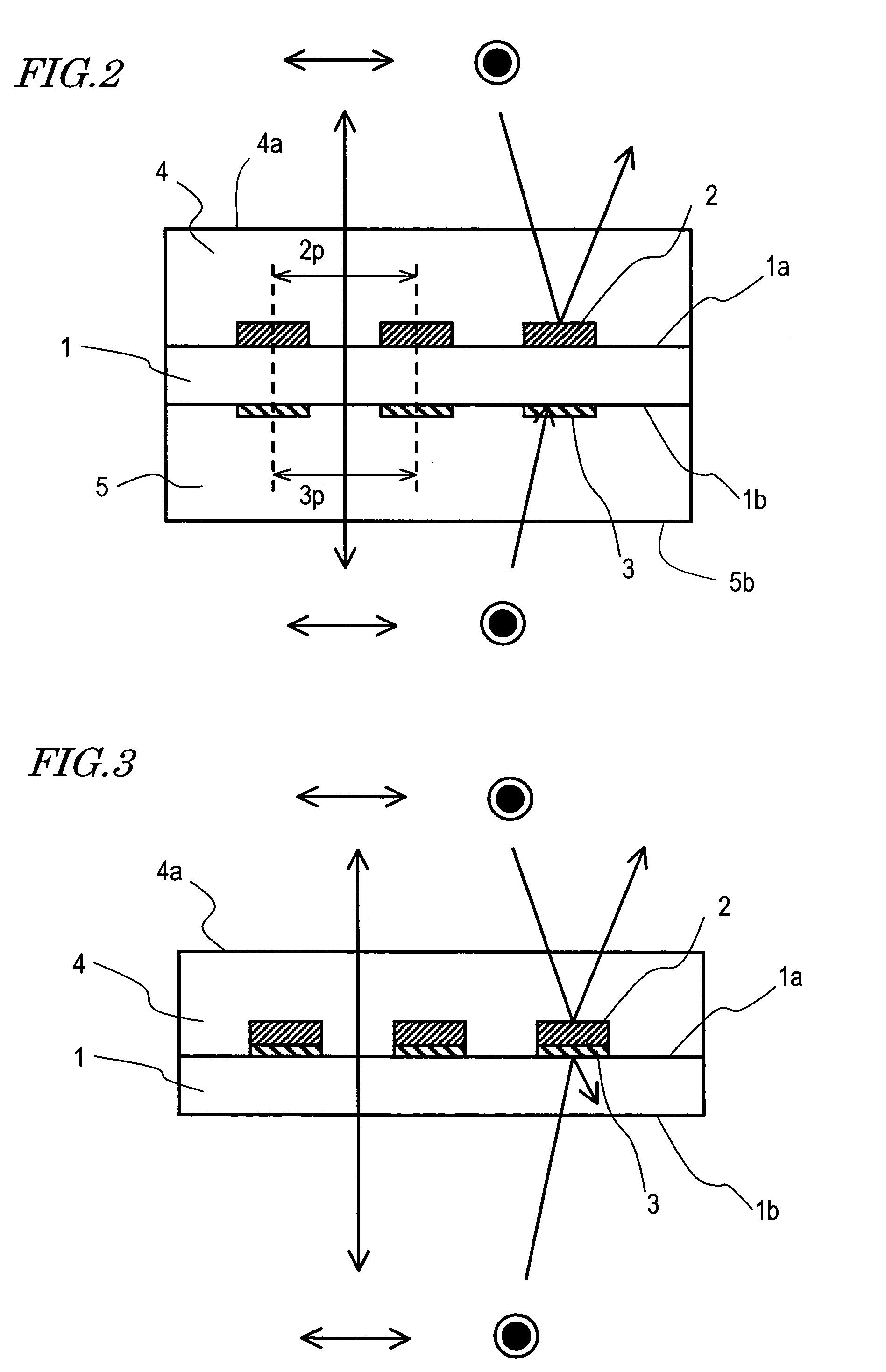
[0055]FIG. 2 illustrates a polarizing optical element according to a first specific preferred embodiment of the present invention.

[0056]The polarizing optical element of this preferred embodiment preferably includes a substrate 1, a first grating layer 2 with a light reflecting property, which is provided on one surface 1a of the substrate 1, a second grating layer 3, which is provided on the other surface 1b of the substrate 1, and protective coatings 4 and 5, which cover these grating layers 2 and 3, respectively.

[0057]The substrate 1 may be made of optically isotropic glass, for example. The first grating layer 2 may be made of an aluminum film with a high light reflecting property and a thickness of 150 nm, for example, and is preferably etched into a grating pattern consisting of multiple lines and spaces. The line width, space width and average grating pitch (2p) may be 80 nm, 70 nm and 150 nm, respectively.

[0058]The second grating layer 3 may be made of a tungsten film with a...

embodiment 2

[0076]FIG. 3 illustrates a polarizing optical element according to a second specific preferred embodiment of the present invention. The polarizing optical element of this preferred embodiment preferably includes a substrate 1, a second grating layer 3, which is provided on one surface 1a of the substrate 1, a first grating layer 2 with a light reflecting property, which is provided on the second grating layer 3, and a protective coating 4, which covers these grating layers 2 and 3. The substrate 1 may be made of optically isotropic glass, for example. The first grating layer 2 may be made of an aluminum film with a high light reflecting property and a thickness of 150 nm, for example, while the second grating layer 3 may be made of a carbon black film with a light absorbing property and a thickness of 150 nm, for example. The first and second grating layers 2 and 3 are preferably etched into the same grating pattern consisting of multiple lines and spaces. The line width, space widt...
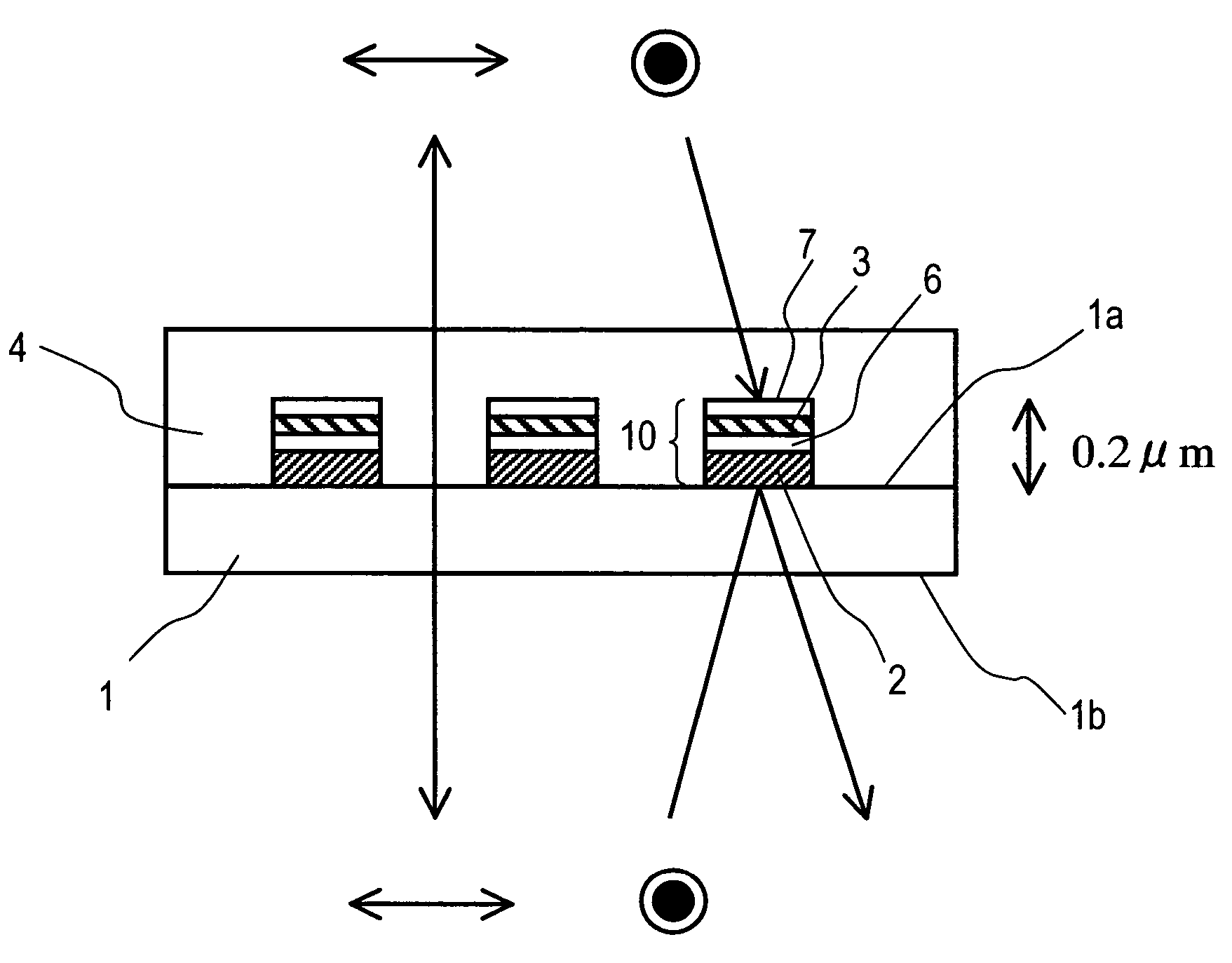
embodiment 3

[0082]FIG. 4 illustrates a polarizing optical element according to a third specific preferred embodiment of the present invention. The polarizing optical element of this preferred embodiment preferably includes a substrate 1, a multilayer structure 10 provided on one surface 1a of the substrate 1, and a protective coating 4 covering the multilayer structure 10. The substrate 1 may be made of optically isotropic glass, for example. The multilayer structure 10 preferably includes a first grating layer 2 with a light reflecting property, a first dielectric layer 6, a second grating layer 3 and a second dielectric layer 7, which are preferably stacked in this order on the surface 1a of the substrate 1. The first grating layer 2 may be made of a silver (Ag) film with a high light reflecting property and a thickness of 150 nm, while the second grating layer 3 may be made of a tungsten film with a light absorbing property and a thickness of 12.8 nm. The first dielectric layer 6 may be an S...


PUM

PropertyMeasurementUnit
reflectanceaaaaaaaaaa
transmittanceaaaaaaaaaa
thicknessaaaaaaaaaa

Abstract

A polarizing optical element changes its optical reflectance and / or transmittance according to a polarization state of incoming light. The optical element includes: a first grating layer including multiple striped portions that extend in a predetermined direction; and a second grating layer including multiple striped portions that extend in that predetermined direction. Average grating pitches of the first and second grating layers are both defined to be shorter than the wavelength of the incoming light. The first grating layer is made of a first material that exhibits a light reflecting property to the incoming light. The second grating layer is made of a second material that reduces the reflection of the incoming light from the first grating layer.

Description

BACKGROUND OF THE INVENTION[0001]1. Field of the Invention[0002]The present invention relates to a polarizing optical element and a display device including the optical element.[0003]2. Description of the Related Art[0004]An absorbing dichroic polarizer is currently used most extensively among various other types of polarizers. The absorbing dichroic polarizer is obtained by adsorbing a compound with light absorption anisotropy (e.g., iodine or a dichroic dye) onto a stretched polymer film and orienting the compound. This polarizer decomposes incoming light into polarization components that cross each other at right angles, absorbs polarization components that are parallel to the absorption axis of the dichroic dye and transmits polarization components that are perpendicular to the absorption axis. Accordingly, the light that has been transmitted through the polarizer becomes linearly polarized light. However, if such an absorbing polarizer is used in a display device, then the tran...

Claims


Application Information

Patent Timeline
Patent Type & Authority Patents(United States)
IPC IPC(8): G11B7/00G02B5/30G02F1/1335G02F1/13357
CPCG02B5/3058G02F1/133536G02F1/13362G02F2203/09B32B2307/416B32B2307/42
Inventor UEKI, SHUNTAGUCHI, TOKIOSHIBATA, SATOSHIMINOURA, KIYOSHISHIMIZU, MASAHIRO
Owner SHARP KK
Why Eureka
Try Eureka