Power system having generator driven by engine

a technology of power system and generator, applied in the direction of electric generator control, process and machine control, motor propulsion transmission, etc., can solve the problems of enlarging the capacity of the inverter circuit, reducing the efficiency of power generation, and preserving the compactness of the system, so as to achieve the effect of increasing the capacity without spoiling the compactness

Inactive Publication Date: 2007-06-26
ORMON CORP +1
View PDF78 Cites 13 Cited by
  • Summary
  • Abstract
  • Description
  • Claims
  • Application Information

AI Technical Summary

Benefits of technology

[0011]The invention is accomplished considering the above-mentioned problem. A first object of the invention is to provide an electric power system whose capacity is increased without spoiling its compactness.
[0013]Accordingly, the inverter circuits provided to the respective armature windings are miniaturized. Therefore, the electric power system having great capacity can be constructed compactly.
[0014]Furthermore, the invention having the multiple inverter circuits provides a construction for controlling operation of the inverter wherein the inverter circuits is prevented from causing the reverse power flow so as to ensure efficient control of generated electric power, and output powers of the inverter circuits are leveled so as to equalize the availabilities and lives of the systems.
[0016]Accordingly, individual output is controlled based on the voltage in the external wire so as to be supplied under the voltage harmonized with the voltage in the external wire. The individual output is also controlled based on the voltage and current of the individual output itself, thereby preventing excessive operation.
[0020]Accordingly, the inverter circuits are controlled so that current flows in the external wire to the consumer. Namely, reverse power flow to the external electric power source can be prevented.
[0022]Accordingly, the main inverter controller is connected to the other inverter controllers through simple communication wirings, thereby reducing manpower for maintenance.

Problems solved by technology

When the electric power generated by the gas cogeneration system causes reverse power flow, the efficiency of power generation falls.
For increasing the capacity of an electric power system such as the gas cogeneration system, enlarging capacity of the inverter circuit poses a problem in respect of retaining the system compact.

Method used


Image

  • Power system having generator driven by engine
  • Power system having generator driven by engine
  • Power system having generator driven by engine

Examples


embodiment 1

[0043]An apparatus for controlling the operation of power conditioners according to the invention is provided for power conditioners having a generation system generating electric power in association with an external electric power system such as a commercial electric power system. The power conditioners are interconnected to the external electric power system, and mutually interconnected through information exchanging means. At least one of the power conditioners monitors the reverse power flow. The power conditioners exchange the monitor information with information of the other power conditioners. Accordingly, outputs of all of the power conditioners are equalized.

[0044]Each of the power conditioners is provided with a transmitter-and-receiver and a communication medium which serve as the information exchanging means. The transmitter-and-receiver is connected through the communication medium to the transmitter-and-receiver of another power conditioner. As the communication mediu...

example 1-1

[0065]Hereinafter, description will be given on an example of the invention according to drawings.

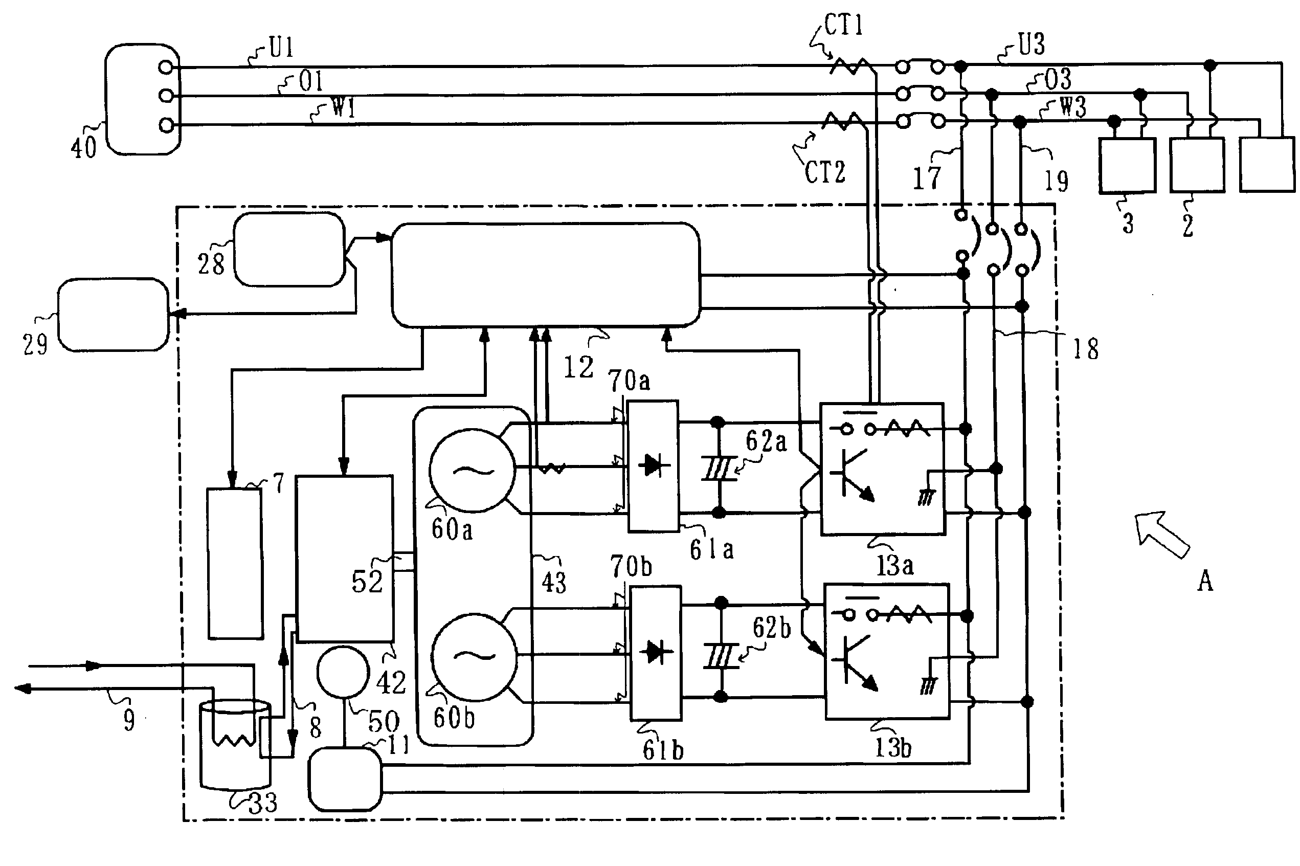
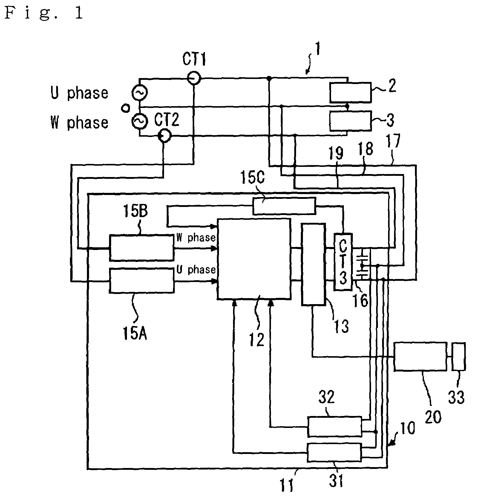
[0066]As shown in FIG. 1, an interconnection system having a power conditioner 10, which associates electric power generated by an electric power generation system 20 with an external electric power system 1 such as a commercial electric power system, controls for restricting output electric power of the power conditioner 10 when the reverse power flow is detected.

[0067]The power conditioner 10 comprises an inverter circuit 13 for converting electric power from the electric power generation system 20 into alternating-current power synchronized with the power from the external electric power source; respective CT input circuits 15A and 15B for U phase line and W phase line for inputting detected signals from respective current detectors (AD converters) CT1 and CT2 for detecting direction and amount of respective current flowing in U phase line and W phase line of the external electric po...

embodiment 1-1

[0075]An embodiment 1-1 according to the invention is shown in FIGS. 3 to 9.

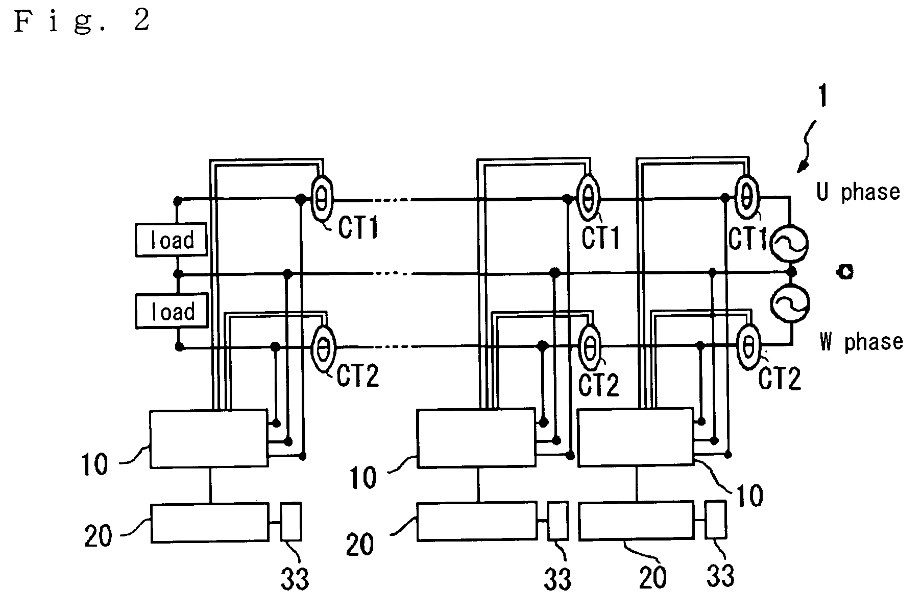
[0076]FIG. 3 illustrates an interconnection system which links multiple cogeneration systems A with the external electric power system 1. In FIG. 3, the external electric power system 1 has three lines for single-phase power. A first (one) load 2 is connected between U phase line and neutral line O of the external electric power system 1. A second (another) load 3 is connected between W phase line and neutral line O of the external electric power system 1.

[0077]Each of the cogeneration systems A has the power conditioner 10, the electric power generation system 20 for supplying electric power to the power conditioner 10, and the exhaust heat recovery device 33. In the power conditioners ranked in order away from the external electric power system 1, the first power conditioner is referred to as “10-1”, the second as “10-2”, and the power conditioner of an ordinal rank n is referred to as “10-n”.

[0078]The pow...


PUM


Abstract

An apparatus for controlling the operation of power conditioners (10) for supplying the generated power to an external power system such as a commercial power system, in which power conditioners (10) are interconnected to an external power system, the power conditioners (10) are interconnected through information exchange means, at least one of the power conditioners (10) monitors the reverse power flow, and the power conditioners (10) exchange the monitor information with information of the other power conditioners (10), thereby equalizing the outputs of all the power conditioners (10). A generator (42) has armature windings (60), and an inverter circuit (13) of the power conditioner (10) provided for each of the armature windings (60) is controlled by cable or radio.

Description

[0001]This application is a continuation of the international application number PCT JP02 / 01053, filed Feb. 7, 2002, (status pending).BACKGROUND OF THE INVENTION[0002]1. Field of the Invention[0003]The invention relates to an electric power system having a generator driven by an engine and power conditioners, and enabled to supply individual electric power generated by the generator and external electric power to load by connecting an output wire of the generator with an external electric power system such as a commercial electric power system through the power conditioners. Especially, it relates to operation control construction of the power conditioners, connection construction of inverter circuits of the power conditioners, and connection construction of multiple electric power systems.[0004]2. Related Art[0005]In recent, a gas cogeneration system attracts public attention as a kind of independent power generation systems. It is a system which provides electric power generated f...

Claims


Application Information

Patent Timeline
Patent Type & Authority Patents(United States)
IPC IPC(8): B60L11/02B61C9/38H02K23/52H02J7/14H02P9/14B60L50/10H02J3/38H02M5/458H02M7/48H02M7/493H02P9/00
CPCH02J3/38H02M5/458H02M7/493H02P9/00H02P9/08
Inventor TOKIWA, MASAYOSHIHIBI, SHINJINAKAMURA, KOTAROMABUCHI, MASAOTOYOURA, NOBUYUKIINOUE, KENICHITANABE, KATSUTAKAOKOBA, YASUYUKI
Owner ORMON CORP
Why Eureka
Try Eureka