
Integrated security in a process plant having a process control system and a safety system

Active Publication Date: 2007-06-26
FISHER-ROSEMOUNT SYST INC
View PDF22 Cites 47 Cited by
  • Summary
  • Abstract
  • Description
  • Claims
  • Application Information

AI Technical Summary

Benefits of technology

[0015]This integration includes using a common data communication structure for both the safety system and the process control system so that applications can send data to and receive data from devices in either system in the same manner, e.g., using the same communication hardware and software. However, the common data communication structure may distinguish process control devices from safety devices using tags, addresses or other fields within the messages sent to or received from the devices, which enables data associated with the process control system to be distinguishable from data associated with the safety system, thereby enabling an application within a user interface to automatically treat this data differently depending on the source (or destination) of the data.
[0016]In one example, display, configuration, control and diagnostic applications may enable writes to be performed to (or reads to be made from) both the process control system devices and the safety system devices, while automatically enforcing security procedures on the writes to the safety system devices that are not needed for the writes to the process control system devices, or vice versa. These writes may be enabled, however, from the same display that distinguishes writes to the safety system from writes to the process control system based on the field of the display into which the data to be written is placed. In this manner, the display, configuration, control and diagnostic applications can make writes to either system without the need to map data from the process control system to the safety system or vice versa.
[0017]Additionally, configuration and diagnostic applications can provide a common interface for performing configuration and diagnostic activities within the process plant for both the process control system and the safety system. In particular, a configuration application may enable a user to configure either or both of the process control system and the safety system and may store the configuration information in a common database with known associations between the process control system devices (logic) and the safety system devices (logic) to make it easier to understand the interrelationships between the control system configuration and the safety system configuration. Still further, a common configuration screen may display both process control system configuration information and safety system configuration information and data generated in one of these systems may be used in the configuration or implementation of the other one of these systems without a separate mapping procedure being performed. This common or integrated configuration application makes it easier to configure the entire plant using a single configuration application which, in turn, eliminates the need to train the same or separate users on different configuration applications.
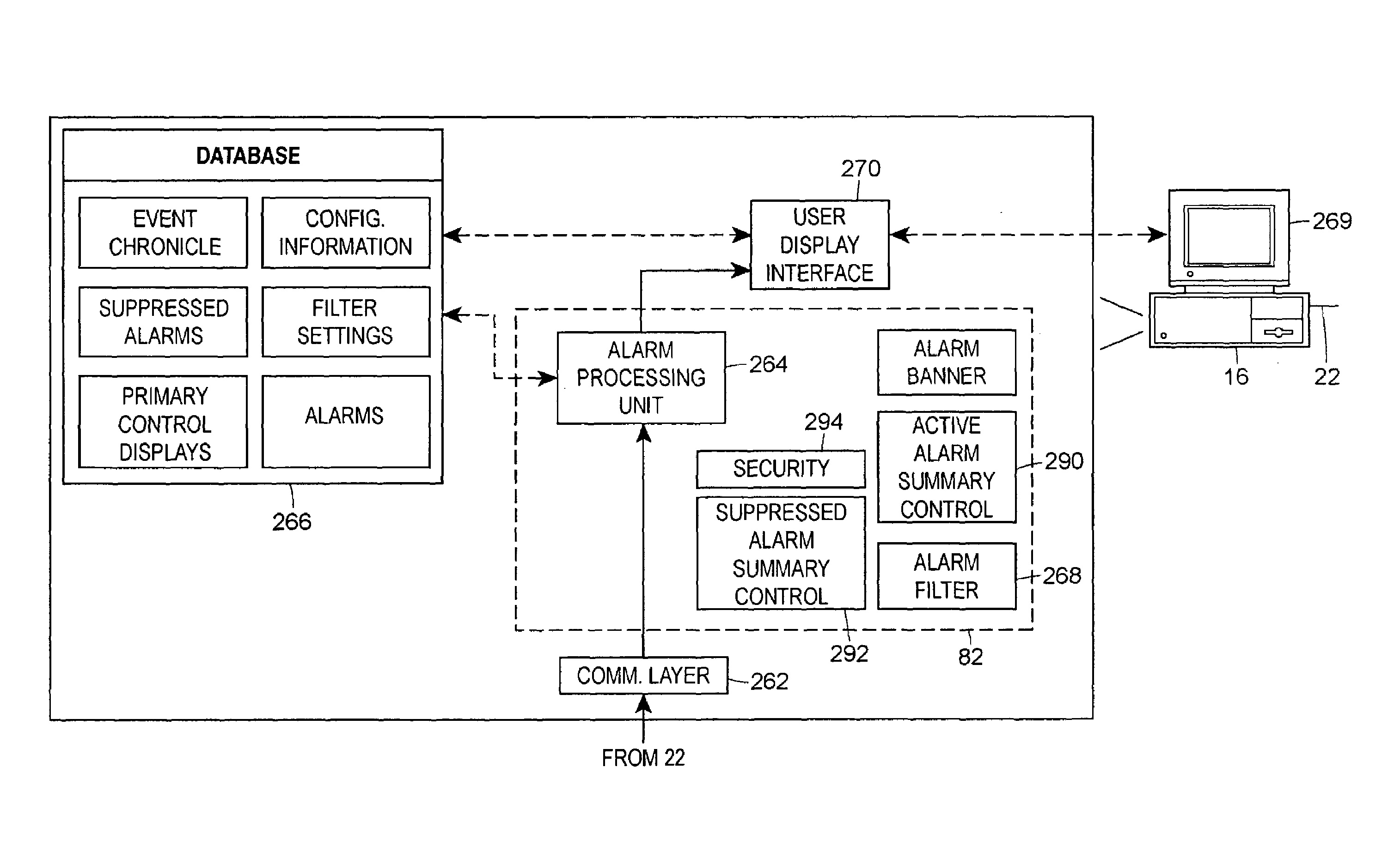
[0018]Likewise, diagnostic applications may be programmed to use data from both the process control system and the safety system to perform integrated diagnostics without losing track of the source of the diagnostic data. For example, an alarm display application may be used to display both process control system alarms and safety system alarms on the same interface, to rank the alarms by priority and to provide some indication of the relationship between these alarms, e.g., that a particular process control system alarm is related in some manner to a particular safety system alarm. Because the alarms are sent to the diagnostic application using a common communication format that distinguishes between safety system devices and process control system devices, the diagnostic application can detect whether an alarm is generated within the process control system or the safety system, and may display both types of alarms without losing track of where and when these alarms were generated.

Problems solved by technology

Furthermore, in many processes, a separate safety system is provided to detect significant safety related problems within the process plant and to automatically close valves, remove power from devices, switch flows within the plant, etc. when a problem occurs that might result in or lead to a serious hazard in the plant, such as a spill of toxic chemicals, an explosion, etc.
Isolation between process controllers and safety controllers is considered important (and is frequently mandated by applicable government standards) because using a process controller to perform safety functions results in the simultaneous failure of the safety functions and the process control functions when that process controller fails.
However, the safety functions become most critical when the process controller fails because, at that time, the process is partially or wholly out of control.
In fact, in some cases, because safety systems do not use the process control system hardware and software infrastructure, different and completely unconnected safety system hardware and software is used at different locations, such as at different nodes, within the same process plant.
In any event, the isolation between the process control system and the safety system leads to a number of different and unconnected safety systems in the same plant that must be configured and monitored separately.
Likewise, different personnel are typically needed to perform configuration, diagnostic and monitoring activities with respect to these different systems, all of which leads to extra costs in terms of configuring and running a process plant that uses a safety system.
Moreover, because the safety system configuration and diagnostic software is different from the control system configuration and diagnostic software, persons must typically be trained separately on these different software programs leading to increased training time.
Unfortunately, traditional control systems do not provide the flexibility to differentiate safety system data from control system data.
As a result, once the safety system information is integrated into the control system applications, the safety system values appear the same as the control system values being displayed to the user, making it difficult to track or differentiate the safety system data.
These data mapping techniques require additional user programming both to set up and to maintain and may lead to erroneous data due to errors introduced by the mapping function.
Still further, security becomes harder to handle in systems which attempt to integrate safety system data into a traditional control system application.
This function is inherently more error prone and hence less secure because it relies on the person programming and maintaining the HMI to ensure that all values from the safety system are correctly mapped into the control system interface.
Furthermore, such a mapping technique makes the HMI safety critical, which complicates the safety instrumentation system, making it much more difficult to test and prove the safety integrity level.
As a result, these known user interface integration systems lack the ability to place safety instrumentation system read and write values directly on a user graphic without requiring mapping between the control and the safety system configurations or without special safety instrumentation control logic located in the safety system controllers that creates a ‘firewall’ between the operator interface and the safety instrumentation system logic, to thereby prevent unauthorized writes to the safety instrumentation system.
Moreover, these known integrated user interface systems lack a secure write mechanism that assures that no corruption of the entered value or path takes place during a write to the safety instrumentation system, and lack unique safety security built into the control system that assures that all writes of values to the safety instrumentation system require special privileges, whether from a process graphic or any other application able to write values in the safety instrumentation system.
As a result, it is difficult for a user to view or understand the configuration of the control system and the safety system in an integrated manner, e.g., in a manner that displays or shows the way in which these two systems interact with one another or in which the devices and logic associated with the different systems are physically and logically interconnected within the plant.
In the same manner, diagnostic applications associated with control and safety systems, such as alarming, testing and other diagnostic tools, have in many cases been performed separately, making it difficult for a single user to understand how problems in one system may effect or relate to problems within the other system.
This non-integrated use and display of diagnostic data makes it more difficult to understand the operation of the entire plant and the manner in which the safety system interacts with the process control system during operation of the plant.
As a result, safety system alarms are essentially presented as process control system alarms, which makes it difficult for users of the alarm display to easily recognize or separate safety system alarms from process control system alarms.
As a result, data pertaining to the actual time that the safety alarms are generated in the safety system is lost, resulting in misleading information for alarm logging, acknowledgement and response purposes.

Method used


Image

  • Integrated security in a process plant having a process control system and a safety system
  • Integrated security in a process plant having a process control system and a safety system
  • Integrated security in a process plant having a process control system and a safety system

Examples


Embodiment Construction

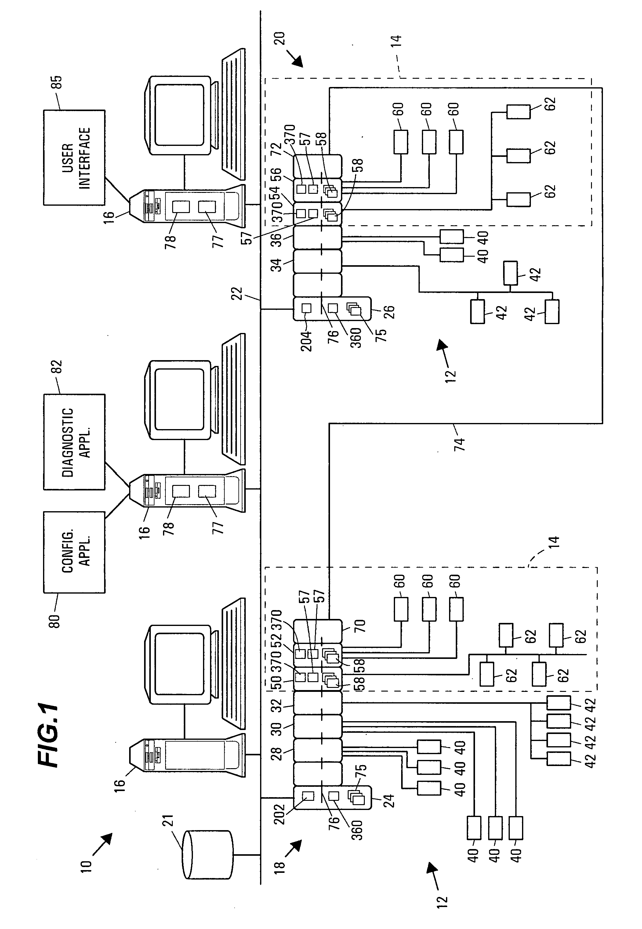
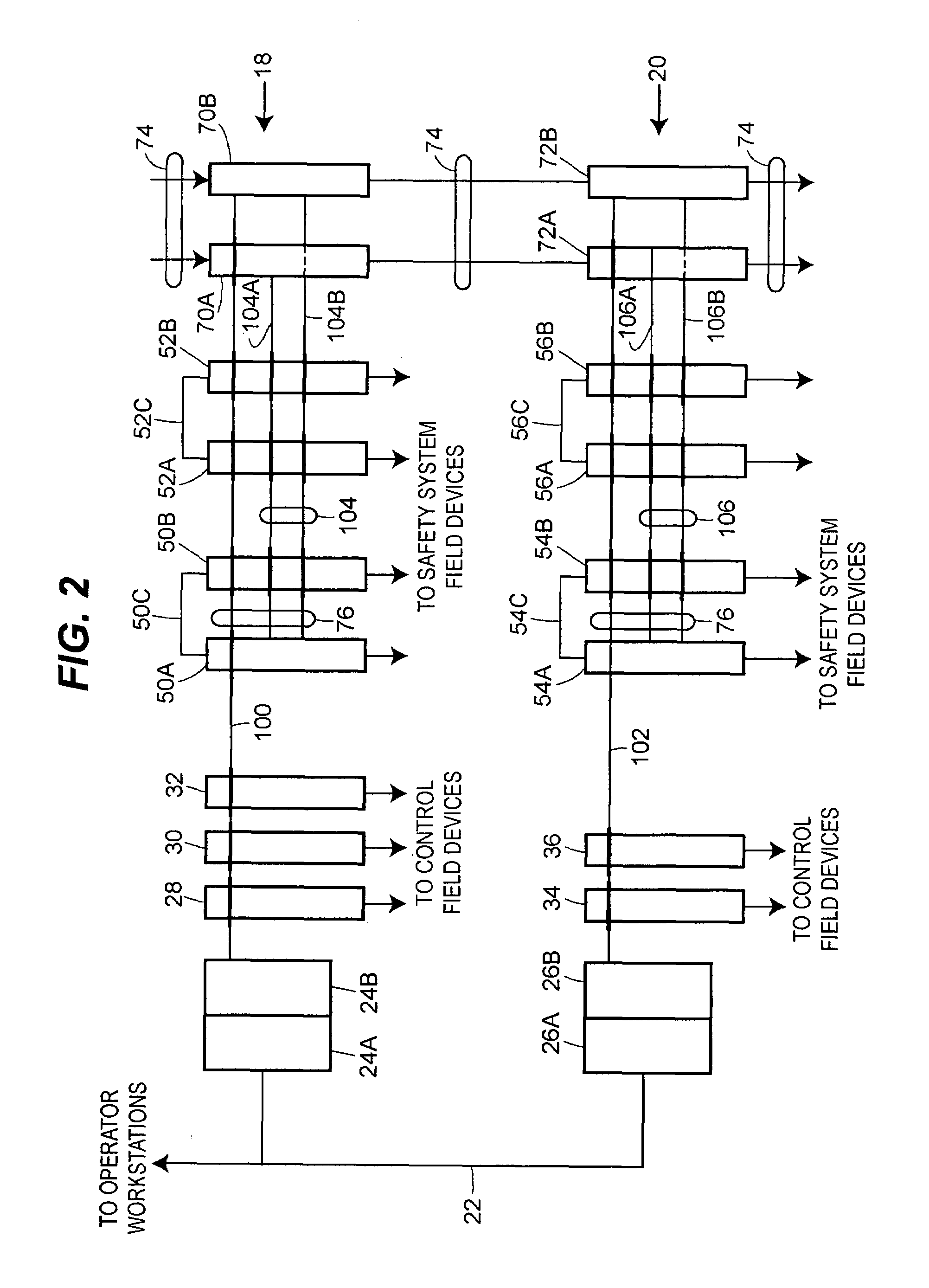
[0026]Referring now to FIG. 1, a process plant 10 includes a process control system 12 integrated with a safety system 14 (indicated by dotted lines), which generally operates as a Safety Instrumented System (SIS) to monitor and override the control provided by the process control system 12 to maximize the likely safe operation of the process plant 10. The process plant 10 also includes one or more host workstations, computers or user interfaces 16 (which may be any type of personal computers, workstations, etc.) that are accessible by plant personnel, such as process control operators, maintenance personnel, configuration engineers, etc. In the example illustrated in FIG. 1, three user interfaces 16 are shown as being connected to two separate process control / safety control nodes 18 and 20 and to a configuration database 21 via a common communication line or bus 22. The communication network 22 may be implemented using any desired bus-based or non-bus based hardware, using any desi...


PUM


Abstract

A process plant includes a safety system that is physically and logically integrated with a process control system such that the safety system and the process control system can use common security, communication and display hardware and software within the process plant while still providing functional isolation between the safety system controllers and the process control system controllers. This integrated process control and safety system uses a common data communication structure for both the safety system and the process control system so that applications can send data to and receive data from devices in either system in the same manner, e.g., using the same communication hardware and software. However, the common data communication structure is set up enable a security application to distinguish process control system devices from safety system devices using tags, addresses or other fields within the messages sent to or received from the devices, which enables data associated with the process control system to be distinguishable from data associated with the safety system, thereby enabling the security application within a user interface to automatically treat this data differently depending on the source (or destination) of the data.

Description

RELATED APPLICATION[0001]This application is a continuation-in-part of U.S. patent application Ser. No. 10 / 352,396, entitled “Process Control System with an Embedded Safety System,” which was filed on Jan. 28, 2003, the disclosure of which is hereby expressly incorporated by reference herein.FIELD OF TECHNOLOGY[0002]The present invention relates generally to safety systems used in process plants and, more particularly, to a safety system that is functionally and logically embedded with or integrated into a process control system of a process plant.DESCRIPTION OF THE RELATED ART[0003]Process control systems, like those used in chemical, petroleum or other processes, typically include one or more process controllers communicatively coupled to at least one host or operator workstation and to one or more field devices via analog, digital or combined analog / digital buses. The field devices, which may be, for example valves, valve positioners, switches and transmitters (e.g., temperature,...

Claims


Application Information

Patent Timeline
IPC IPC(8): G06F1/24G05B9/03G05B9/02G05B19/00G05B19/02G05B19/042G05B19/048G05B19/418G05B23/00G05B23/02G06F1/00
CPCG05B19/042G05B23/027G05B2219/24159G05B2219/25428G05B19/0428G05B19/048
Inventor SCOTT, CINDYLAW, GARYOTT, MICHAEL G.SHERRIFF, GODFREY
Owner FISHER-ROSEMOUNT SYST INC
Learn More