
Wall surfacing template

a wall surface and template technology, applied in the field of building wall surface templates, can solve the problems of high cost and time consumption of masonry construction, long lead time of bricks, and time-consuming removal of paper templates of prior art, and achieve the effect of convenient rapid removal of templates and high strength

Inactive Publication Date: 2007-07-03
DASA ENTERPRISES
View PDF33 Cites 14 Cited by
  • Summary
  • Abstract
  • Description
  • Claims
  • Application Information

AI Technical Summary

Benefits of technology

[0007]The template of this invention is formed of nonwoven spunbond polyester material. The template when used in a conventional process of forming a variable depth building surface, such as a simulation of common construction materials such as brick, stone, or tile building surfaces, expedites the application of the stencil pattern because the template is of high strength which facilitates rapid removal of the template after the application of the exterior color layer. The material may be reinforced with strands or reinforcing, such as fiberglass.
[0008]It is an object of the present invention to provide a template for the preparation of a variable depth building surface which is effectively removed from the wall surface with minimal fragmentation.

Problems solved by technology

Masonry construction is, however, costly and time-consuming to employ.
Moreover, brick typically has a long lead time to procure, and hence the application of a brick finish can be a bottleneck in building construction if the desired brick is not readily available.
However, the paper templates of the prior art can be time-consuming to remove, as the paper is prone to tearing in the process of removal, especially if the second layer of coating has been allowed to set for too long.
Rarely is it possible to remove the template in a single operation.

Method used


Image

  • Wall surfacing template
  • Wall surfacing template

Examples


Embodiment Construction

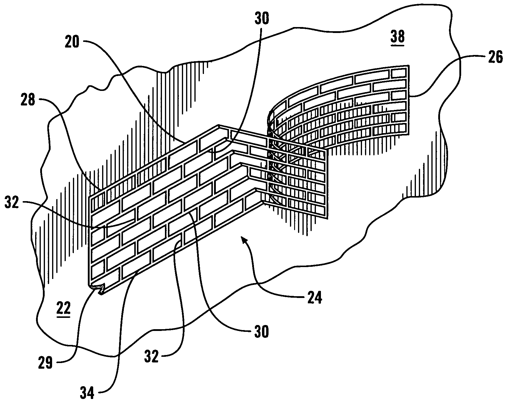
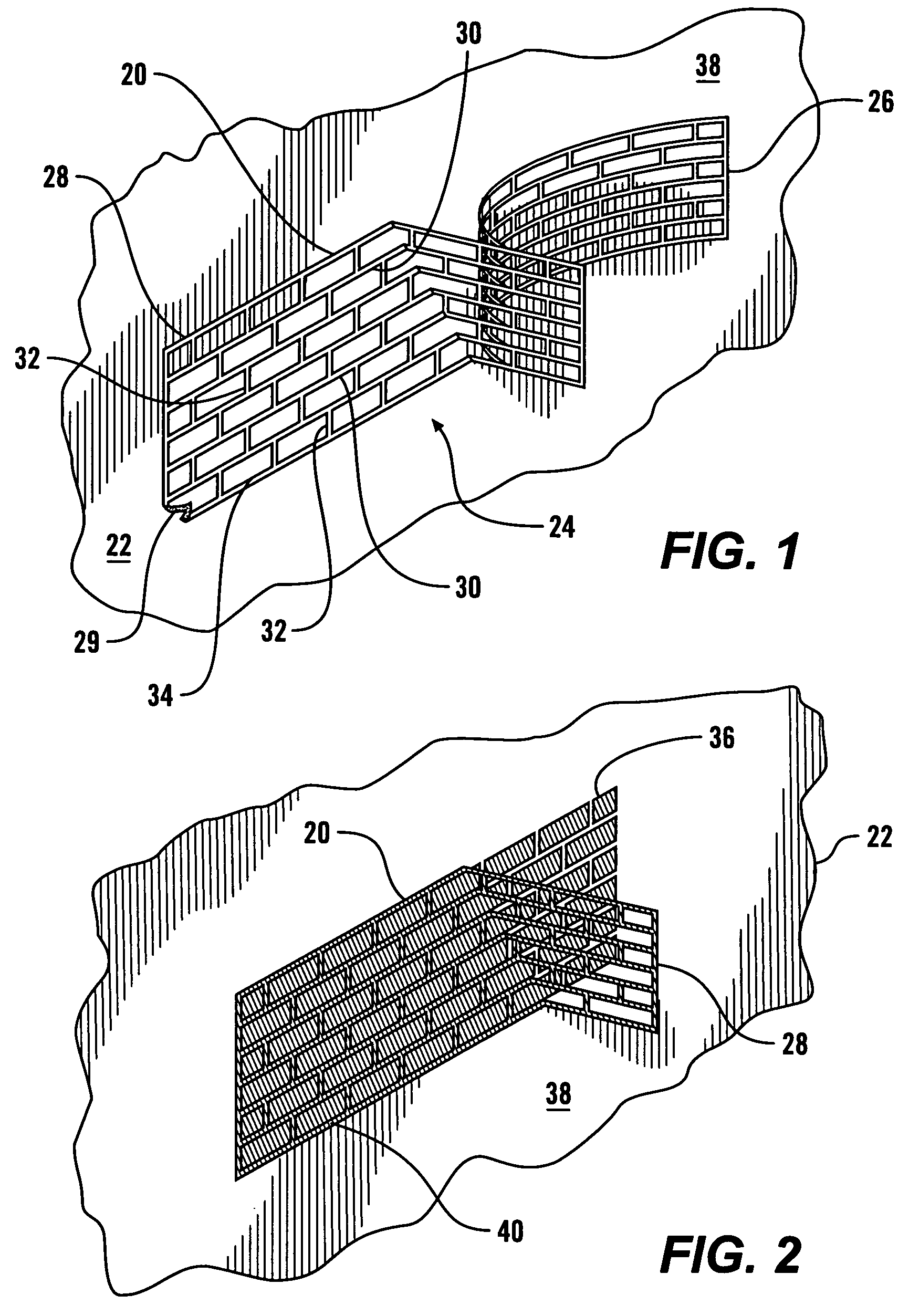
[0012]Referring more particularly to FIGS. 1-2, wherein like numbers refer to similar parts, a template 20 is shown applied to a wall surface 22. The template 20 is provided to an installer as part of a template assembly 24 comprised of the adhesive backed template connected to a release liner backing sheet 26. The template 20 is formed from a substrate 28 which is a cut sheet of substrate material 28 having a pressure-sensitive adhesive coating 29 or other type of adhesive.

[0013]The adhesive may be an acrylic based adhesive or a rubber based adhesive, or other adhesive selected to adhere to the wall surface to which the template is intended to be temporarily attached. An aggressive adhesive, for example, may be used when the template is being attached to a rough wall surface.

[0014]The backing sheet 26 is cut to the same outline as the substrate 28 and protects the adhesive until use, at which point the backing sheet 26 is releasably removed from the substrate 28 without impairing t...


PUM

PropertyMeasurementUnit
thickaaaaaaaaaa
thickaaaaaaaaaa
sizeaaaaaaaaaa

Abstract

A template assembly for use in the production of a variable depth building wall surface, which may be simulative of multiple units separated by mortar joints, such as a simulated brick, stone, tile, or mosaic surface. The template assembly is formed of a backing sheet which is releasably attached to a substrate formed of nonwoven spunbond polyester material, which may be fiberglass reinforced. The substrate is a unitary sheet having a plurality of upwardly extending strips connected by a plurality of sidewardly extending strips. The strips define a plurality of openings within which simulated building units may be formed. A first layer is applied to a wall surface, the template backing is removed and the template adhered to the first layer, and then a second layer is applied over the template. When the template is removed, those areas corresponding to the template strips will be recessed from the second layer.

Description

BACKGROUND OF THE INVENTION[0001]The present invention relates to templates for the preparation of building wall surfaces.[0002]Brick and stone have been used as building components for thousands of years. Historically, modular brick units were used as structural elements, united by mortar, to define vertical walls, columns, and lintels. In more recent times, when steel frame or wood stick construction has been favored, brick has been applied as a veneer to a substructure. When used as veneer, the bricks still convey an appearance of solidity and permanence. Stone, tile, and other mortar-joined building elements produce a variable depth building surface with the mortar joint usually recessed from the surfaces of the building elements. The variable depth building surface provides an attractive appearance which changes with the position of the sun, and climatic conditions.[0003]Masonry construction is, however, costly and time-consuming to employ. Moreover, brick typically has a long ...

Claims


Application Information

Patent Timeline
Patent Type & Authority Patents(United States)
IPC IPC(8): B32B3/10B44F7/00B44F9/00E04C1/00E04F13/00E04F15/00E04F19/00
CPCB44D2/007B44F11/06E04F21/04Y10T428/1471Y10T428/24322Y10T428/24273
Inventor PETERSON, ROBBIE R.
Owner DASA ENTERPRISES
Learn More