Light quantity distribution control element and optical apparatus using the same

a technology of light quantity and control element, which is applied in the direction of mountings, coatings, instruments, etc., can solve the problems of increased cost, difficulty in increasing speed, and difficulty in obtaining high-quality recorded images

Active Publication Date: 2007-07-03
PANASONIC CORP
View PDF9 Cites 4 Cited by
  • Summary
  • Abstract
  • Description
  • Claims
  • Application Information

AI Technical Summary

Benefits of technology

[0008]Therefore, with the foregoing in mind, the disclosed concepts present an inexpensive light quantity distribution control elements that can correct non-uniformity of light quantity properly, and an optical apparatus using the same such like an information recording / reproducing apparatus, an image pickup device and an optical scanning device, and an image-forming apparatus using the optical scanning device.
[0011]A light quantity distribution control that can correct the non-uniformity in the light quantity properly can be realized simply by varying the convex height in the antireflective structure, depending on the incident region of the light, so that the transmittance varies depending on the incident region of the light. As a result, light quantity distribution control elements that are suitably used to correct the non-uniformity in the light quantity in an optical scanning device or the like properly can be provided. Then, when an image-forming apparatus is configured by using an optical scanning device on which the light quantity distribution control element or the light quantity distribution control lens is mounted, high quality recorded image can be obtained. Furthermore, when information is reproduced with an information recording / reproducing apparatus, using the light quantity distribution control element or the light quantity distribution control lens, optimal recording / reproduction of information can be performed. Moreover, when an image pickup device is constituted by using the light quantity distribution control element or the light quantity distribution control lens, high quality imaging with reduced non-uniformity in light quantity can be performed.

Problems solved by technology

However, in order to increase the number of the deflection reflective surface of the polygon mirror, it is necessary to increase the inner diameter and thus it is difficult to increase the speed.
Therefore, the light quantity on the photoconductor drum becomes non-uniform, so that it is difficult to obtain high quality recorded images.
However, with the above-described configurations, the cost is increased and variation in light quantity also is increased.
Moreover, when an image pickup device is constituted by using the light quantity distribution control element or the light quantity distribution control lens, high quality imaging with reduced non-uniformity in light quantity can be performed.

Method used


Image

  • Light quantity distribution control element and optical apparatus using the same
  • Light quantity distribution control element and optical apparatus using the same
  • Light quantity distribution control element and optical apparatus using the same

Examples


first embodiment

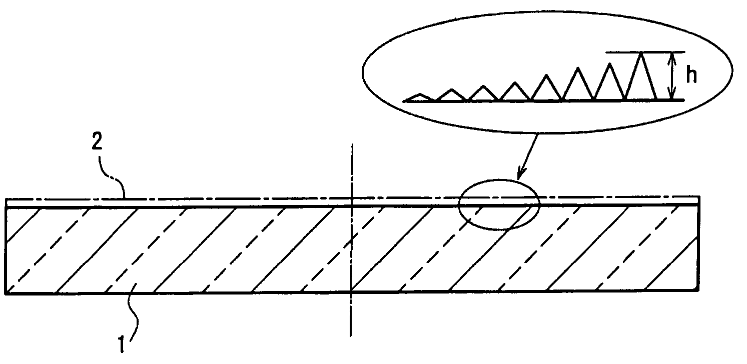
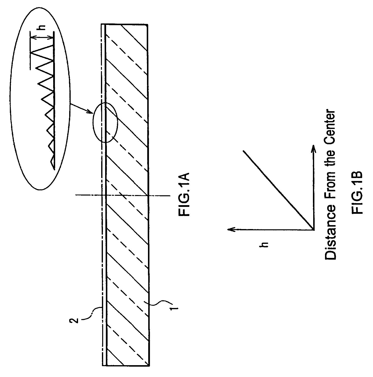
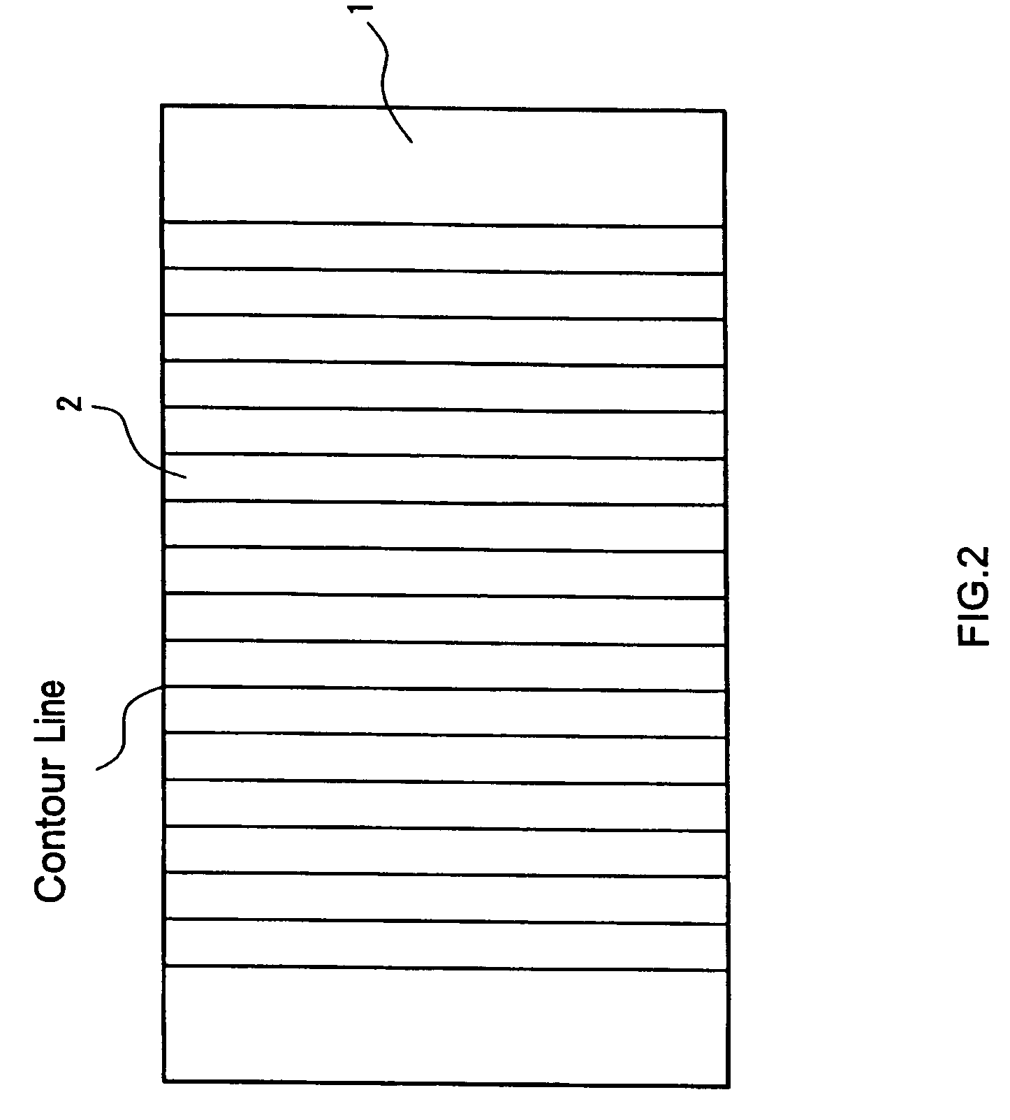
[0026]FIG. 1A is a schematic cross-sectional view showing a light quantity distribution control element in a first embodiment. And FIG. 1B is a graph showing a height distribution of an antireflective structure in a first embodiment. FIG. 2 is a schematic diagram showing the lines of equal convex height in a antireflective structure constituting the light quantity distribution control element. FIG. 3 is a schematic perspective view showing the antireflective structure constituting the light quantity distribution control element.

[0027]As shown in FIGS. 1 to 3, the light quantity distribution control element of this embodiment includes a substrate 1 of 20 mm×20 mm×3 mm made of a material that transmits light, such as quartz, acryl and polycarbonate, and an antireflective structure 2 provided on a surface of the substrate 1. In this embodiment, a conical antireflective structure (periodic structure having conical convexities) of a pitch of 0.15 μm is formed as the antireflective struct...

second embodiment

[0036]FIG. 7A is a schematic cross-sectional view showing a light quantity distribution control lens in the second embodiment. And FIG. 7B is a graph showing a height distribution of an antireflective structure in a second embodiment.

[0037]As shown in FIGS. 7A and 7B, the light quantity distribution control lens of this embodiment includes a plano-convex lens 4 having an effective diameter of 20 mm and made of an optical glass, resin or the like as a lens main body, and a antireflective structure 2 provided on the smooth surface of the plano-convex lens 4.

[0038]As the antireflective structure 2, the same structures as described in the first embodiments can be used. In other words, the antireflective structure 2 has a structure in which the convex height h varies depending on the transmission region of light. With this as the basis, the antireflective structure 2 can be configured in various embodiments as described in the first embodiments.

[0039]The light quantity distribution contr...

third embodiment

[0043]FIG. 8 is a schematic structural view showing an information recording / reproducing apparatus in the third embodiment.

[0044]As shown in FIG. 8, the information recording / reproducing apparatus in the third embodiment includes a semiconductor laser 5 that emits laser light as a light source. The laser light emitted by the semiconductor laser 5 passes through a diffraction grating 6 and then is let be collimated light by a collimator lens 7. This collimated light passes through a light quantity distribution control element 8 as described in the first embodiment and a beam splitter 9, and then is focused on an optical disk 11 as an information carrier by an optical lens 10 as focusing means.

[0045]The reflected light from the optical disk 11 passes through the objective lens 10 again and becomes collimated light, and thereafter the traveling direction is changed by 90 degrees by the beam splitter 9 and the light is incident to a light-receiving element 13 with a detection lens 12.

[0...


PUM

PropertyMeasurementUnit
aspect ratioaaaaaaaaaa
convex heightaaaaaaaaaa

Abstract

A light quantity distribution control element includes a substrate of 20 mm×20 mm×3 mm made of a material that transmits light, such as optical glass or acryl, and a antireflective structure provided on a surface of the substrate. As the antireflective structure, a conical antireflective structure of a pitch of 0.15 μm (periodic structure having conical convexities) is formed. This corresponds to a antireflective structure having a pitch of a wavelength or less in the ultraviolet band (150 nm to 400 nm) at the time when ultraviolet light is used as incident light.

Description

BACKGROUND[0001]1. Technical Field[0002]The disclosed concepts relate to a light quantity distribution control element and a light quantity distribution control lens used preferably to correct non-uniform light quantity in optical scanning devices or the like, and an information recording / reproducing apparatus, an image pickup device and an optical scanning device using the same, and an image-forming apparatus using the optical scanning device.[0003]2. Description of the Background Art[0004]A number of optical scanning devices used in laser beam printers or the like include a semiconductor laser as a light source, a first imaging optical system for imaging light flux from the light source linearly on a rotary polygon mirror in order to correct the pyramidal error of the rotary polygon mirror, a polygon mirror as the rotary polygon mirror and a second imaging optical system for imaging uniform spots at a constant velocity on a photoconductor drum, which is a surface to be scanned.[00...

Claims


Application Information

Patent Timeline
Patent Type & Authority Patents(United States)
IPC IPC(8): G02B5/18G02B1/11G02B7/02
CPCG02B1/118G02B7/02Y10S359/90
Inventor YOSHIKAWA, MOTONOBUYAMAMOTO, YOSHIHARUTANAKA, YASUHIROYAMAGATA, MICHIHIROYAMAGUCHI, HIROSHI
Owner PANASONIC CORP
Why Eureka
Try Eureka