
Weak coupling bridge for optical fiber cores

a coupling bridge and core technology, applied in the field of high-power fiber lasers, can solve the problems of entanglement of fundamental (in-phase) mode structure, and achieve the effect of strengthening the coupling between the connected cores and strengthening the weak coupling

Inactive Publication Date: 2007-07-10
AIR FORCE GOVERNMENT OF THE US SEC THE
View PDF8 Cites 26 Cited by
  • Summary
  • Abstract
  • Description
  • Claims
  • Application Information

AI Technical Summary

Benefits of technology

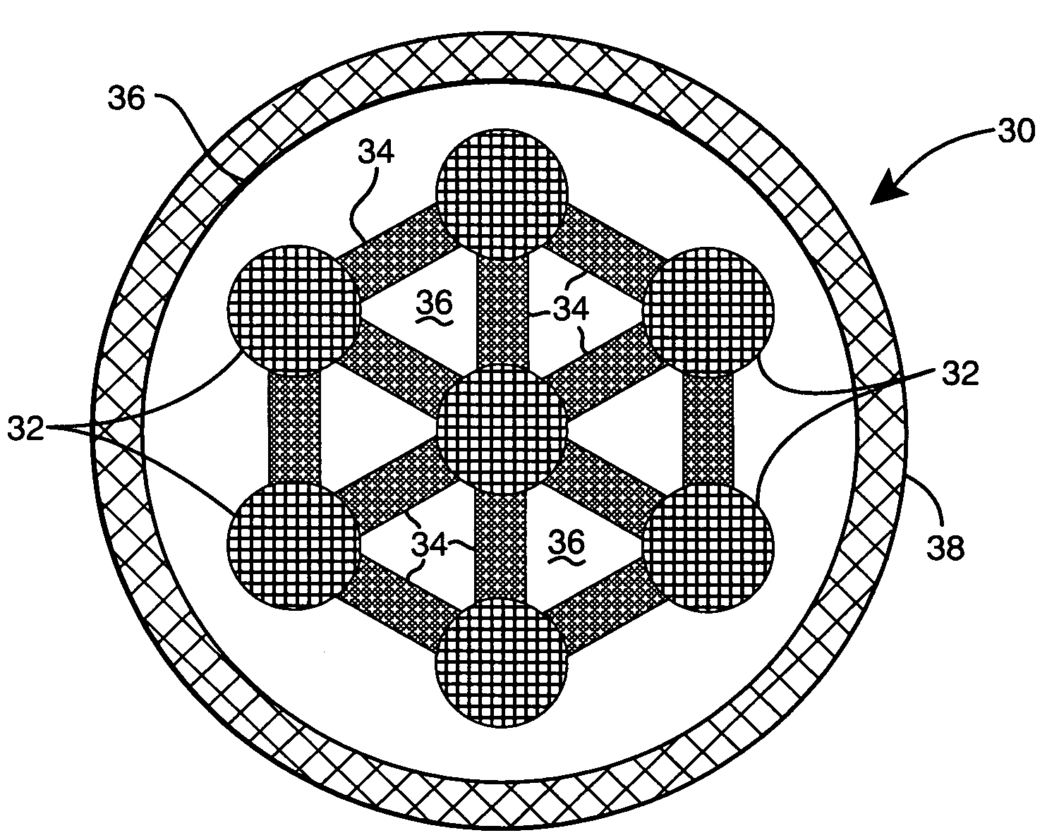
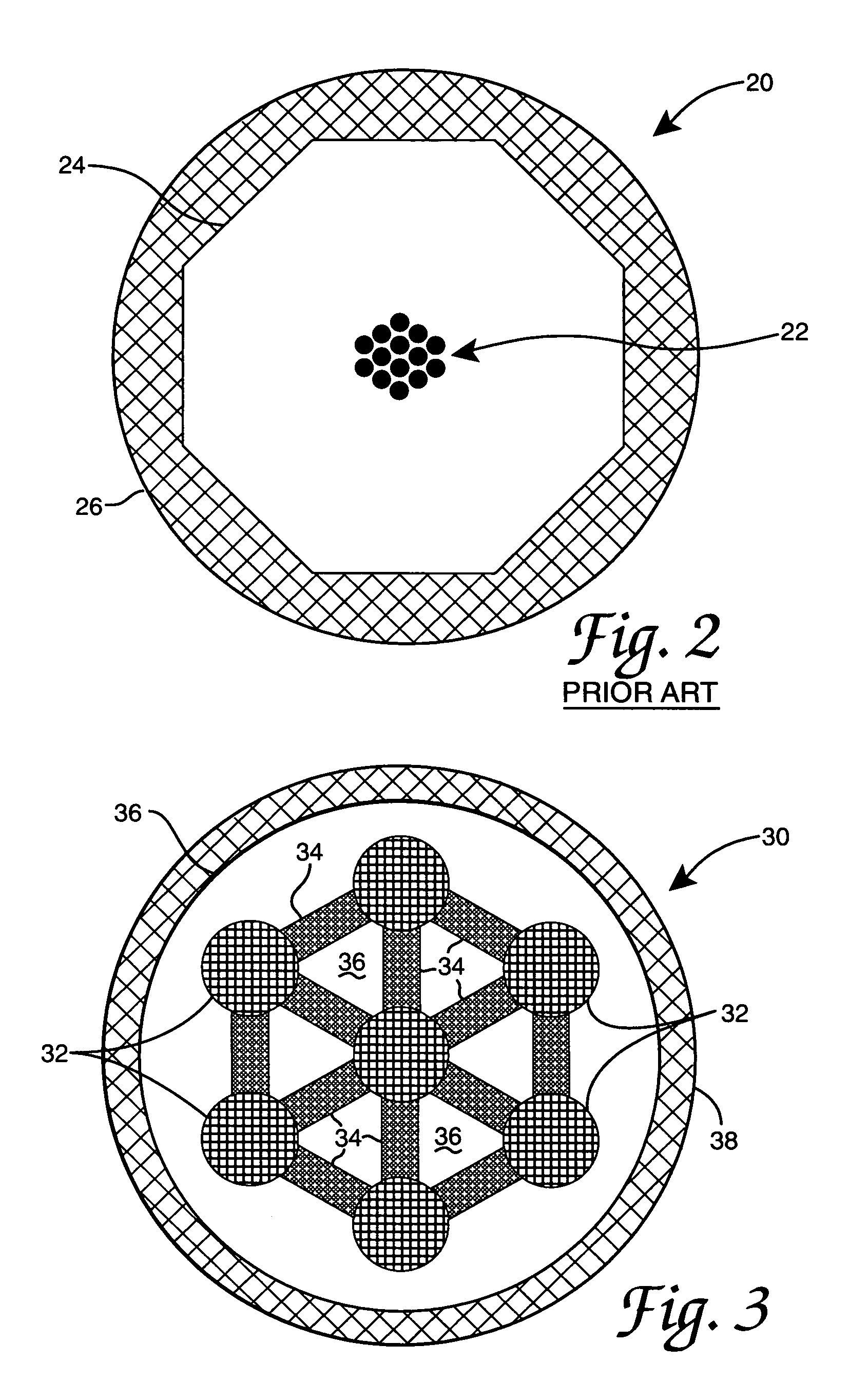
[0013]Briefly, cores in a multicore optic fiber are connected by optical ducts, also referred to as “bridges,” made of material having a refractive index that is somewhat higher than that of the inner cladding in which the cores are embedded. The bridges function like wave-guides linking the cores, but with a cut-off frequency that is greater than the frequency of the laser radiation. This enhances the weak coupling between the connected cores through an evanescent field that is sufficient to synchronize the phase of the light in the cores, but not strong enough to possibly induce instabilities in the fundamental (in-phase) mode structure. The bridges are thus capable of strengthening the coupling between the connected cores, even when the distance between them is increased to a large value. Without the bridges, the coupling, i.e., the rate at which light power is transferred between adjacent cores, decreases exponentially with the inter-core distance, limiting that distance to a few core diameters.
[0014]The bridges of the present invention allow the distance between adjacent cores to be increased in order to reduce heat generation inside the cores, while maintaining the optical coupling responsible for synchronizing the phasing of the individual core fields. Furthermore, by doping the bridges with the same gain-producing rare-earth ions used in the cores, another mechanism is introduced to favor the in-phase supermode, since anti-phasing would produce minima (nodes) in intensity half-way between cores of opposite phase, thereby resulting in smaller gain for the anti-phase supermodes in comparison to that of the in-phase supermode.

Problems solved by technology

This enhances the weak coupling between the connected cores through an evanescent field that is sufficient to synchronize the phase of the light in the cores, but not strong enough to possibly induce instabilities in the fundamental (in-phase) mode structure.

Method used


Image

  • Weak coupling bridge for optical fiber cores
  • Weak coupling bridge for optical fiber cores
  • Weak coupling bridge for optical fiber cores

Examples


Embodiment Construction

[0019]FIG. 3 is a cross-section of multicore optic fiber 30 of the present invention. Fiber 30 includes cores 32, bridges 34, inner cladding 36, and outer cladding 38. Each core 32 is laterally connected to adjacent cores 32 by bridges 34. Cores 32 and bridges 34 are embedded in inner cladding 36. Outer cladding 38 circumscribes inner cladding 36.

[0020]Each core 32 is a single transverse-mode optical wave-guide consisting of silicate glass within which is dispersed, or “doped,” a concentration of ions of one, or more, rare-earth species. This doping achieves a population inversion in each of cores 32 through absorption of radiation emitted by a pump source (not shown), such as an array of semiconductor lasers; also known as “pumping.” The pump source is designed to efficiently couple radiation into the pure silicate inner cladding 36 surrounding cores 32.

[0021]Outer cladding 38 surrounds inner cladding 36 and is composed of material having a lower refractive index than that of pure ...


PUM


Abstract

A bridge for weakly coupling optical cores in a multicore fiber. An inner cladding surrounds each of the cores. A plurality of bridges laterally connects each of the cores to adjacent cores. The bridges run the length of the fiber. Each bridge enhances the weak evanescent coupling between the cores for frequencies of the light being transmitted by the fiber that are smaller than a cut-off frequency. This permits increased spacing of the cores. This abstract is provided to comply with the rules requiring an abstract, and is intended to allow a searcher or other reader to quickly ascertain the subject matter of the technical disclosure. It is submitted with the understanding that it will not be used to interpret or limit the scope or meaning of the claims.

Description

STATEMENT OF GOVERNMENT INTEREST[0001]The invention described herein may be manufactured and used by or for the Government for governmental purposes without the payment of any royalty hereon.BACKGROUND OF THE INVENTION[0002]The present invention is related to the field of high-power fiber lasers and, more particularly, comprises a structure for providing passive phase synchronization and mode discrimination favoring the in-phase supermode for rare-earth-doped fiber lasers and amplifiers.[0003]Due to their intrinsically single transverse-mode wave-guide structure, fiber lasers made from hair-thin high-quality silicate glass are unique in maintaining very high mode quality, even during high-power operation. Moreover, due to their large surface area-to-volume ratio, fiber lasers also possess excellent thermal management properties. Hence, relative to other types of lasers, such devices produce extremely high output beam brightness, defined as the beam power divided by the product of th...

Claims


Application Information

Patent Timeline
IPC IPC(8): G02B6/02
CPCG02B6/02042
Inventor BOCHOVE, ERIK J.
Owner AIR FORCE GOVERNMENT OF THE US SEC THE
Learn More