Closed loop analog gyro rate sensor

a closed loop, gyro rate technology, applied in the direction of acceleration measurement using interia force, instruments, devices using electric/magnetic means, etc., can solve the problems of high power consumption, large package size, and limited cost of tactical grade inertia measuring units, so as to achieve accurate and low cost measurement and automatically null out the modulation

Inactive Publication Date: 2007-07-17
L 3 COMM CORP
View PDF1 Cites 24 Cited by
  • Summary
  • Abstract
  • Description
  • Claims
  • Application Information

AI Technical Summary

Benefits of technology

[0031]Accordingly, the present invention relates to a system and method for accurate and low cost measurement of rate and linear acceleration in a high volume design. The method includes automatically nulling out the modulation using closed loop electronics without the need for mechanical sensor trimming or extraordinary processing tolerances.

Problems solved by technology

However, the use of tactical grade inertia measuring units has been limited by their cost to high-priced systems such as military aircraft, missiles, and other special markets.
The cost of inertia measuring units is dominated by the expensive discrete gyroscopes and discrete accelerometers and attendant electronics used to drive and convert these signals for use in computer systems.
Other problems with inertial measuring units are high power consumption and large package size.
The problems of high power consumption and large package size further limit applications to larger equipment boxes in equipment racks.
Still other problems with the prior art, discussed below in more detail, include a limitation in rate bias accuracy caused by modulation of the accelerometer due to coupling from the dither motion which causes phase angle sensitivity of the rate data.
A further limitation in rate bias accuracy is caused by modulation of the accelerometer due to coupling of external vibration components coupling into the rate data.
Above referenced U.S. Pat. No. 5,005,413 describes accelerometers utilizing vibrating force transducers that require materials with low internal damping to achieve high Q values that result in low drive power, low self-heating and insensitivity to electronic component variations.
Transducer materials for high-accuracy instruments also require extreme mechanical stability over extended cycles at high stress levels.
Various issues with the use of vibrating beam force transducers in accelerometers include the need to operate the device in a substantial vacuum such that the beams can vibrate at their natural frequency without loss of energy from viscous damping.
The high doping levels in the epitaxial layer required to form the vibrating beams make the material inherently unstable.
Thus, the output of the vibrating beams tends to degrade over time and with exposure to thermal environments.
The nature of vibrating beam transducers causes accelerometer design and analysis to be relatively complex as compared to that of simpler force rebalance accelerometers and their larger size reduces the quantity of accelerometers which can be fabricated in a single wafer of silicon substrate so that vibrating beam accelerometers are inherently more expensive to produce than miniature force rebalance accelerometers.
The two accelerometers tend to vibrate at slightly different frequencies due to slight mass mismatch.
The complexity of the link is driven by practical considerations involved in adapting the link to accommodate both, the pivot flexure and the two link-to-accelerometer flexures.
Although the device described in above referenced U.S. Pat. No. 5,341,682 functions for the purposes intended, its exact behavior is difficult to predict and / or model analytically.
For example, the complex shape of prior links results in spring rates which are asymmetrical and a shape which is difficult to solve analytically.
Additionally, constructing the shape previously taught results in flexures whose thicknesses and hence vibration properties are difficult to control.
However, true orthogonality is not achieved between the dither motion and the Coriolis acceleration sensing direction in the normal manufacturing process.
This axis misalignment in conjunction with a phase shift causes a rate bias error which limits performance.
However, such capacitive steering requires very small gaps, on the order of microns, between the sensing mass and stationary members to generate sufficient applied force.
Given the very small gaps necessary, actual implementation of this axis alignment feature is difficult in a normal manufacturing setting using conventional processing methods.
The prior art as discussed above, however, has proven unsatisfactory.
Generally, the Coriolis rate sensors have the problem of difficult fabrication, lengthy analysis and hard to implement axis-alignment capability.
The result of such shortcomings is less than optimal yields, low quantity of sensors per wafer, higher design costs and limited rate bias performance.

Method used


Image

  • Closed loop analog gyro rate sensor
  • Closed loop analog gyro rate sensor
  • Closed loop analog gyro rate sensor

Examples


Embodiment Construction

[0054]The following description is presented to enable any person of ordinary skill in the art to make and practice the present invention. Modifications to the preferred embodiment will be readily apparent to those of ordinary skill in the art, and the disclosure set forth herein may be applied to other embodiments and applications without departing from the spirit and scope of the present invention and the appended claims. Thus, the present invention is not intended to be limited to the embodiments described, but is to be accorded the broadest scope consistent with the claims appended hereto and the disclosure set forth herein.

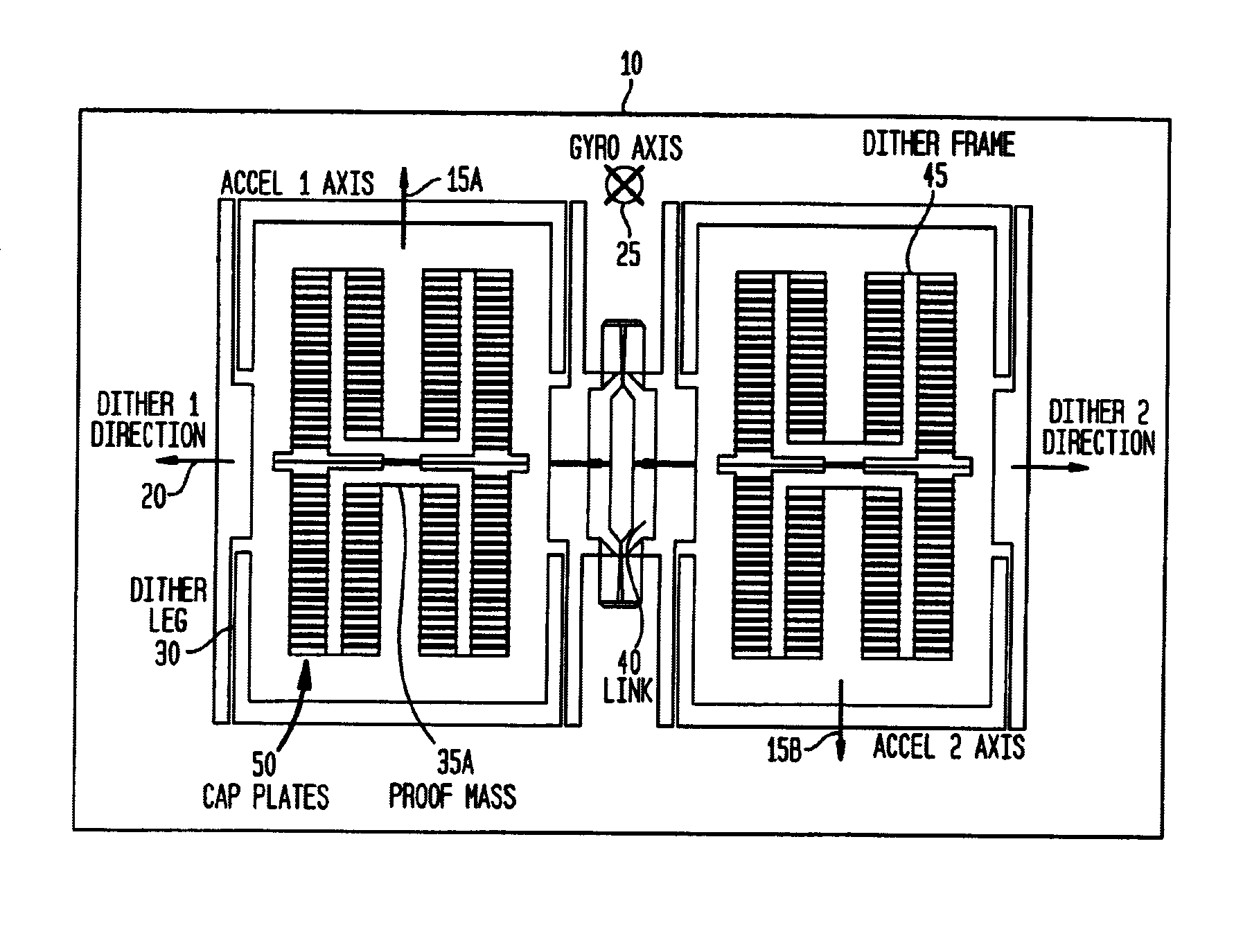
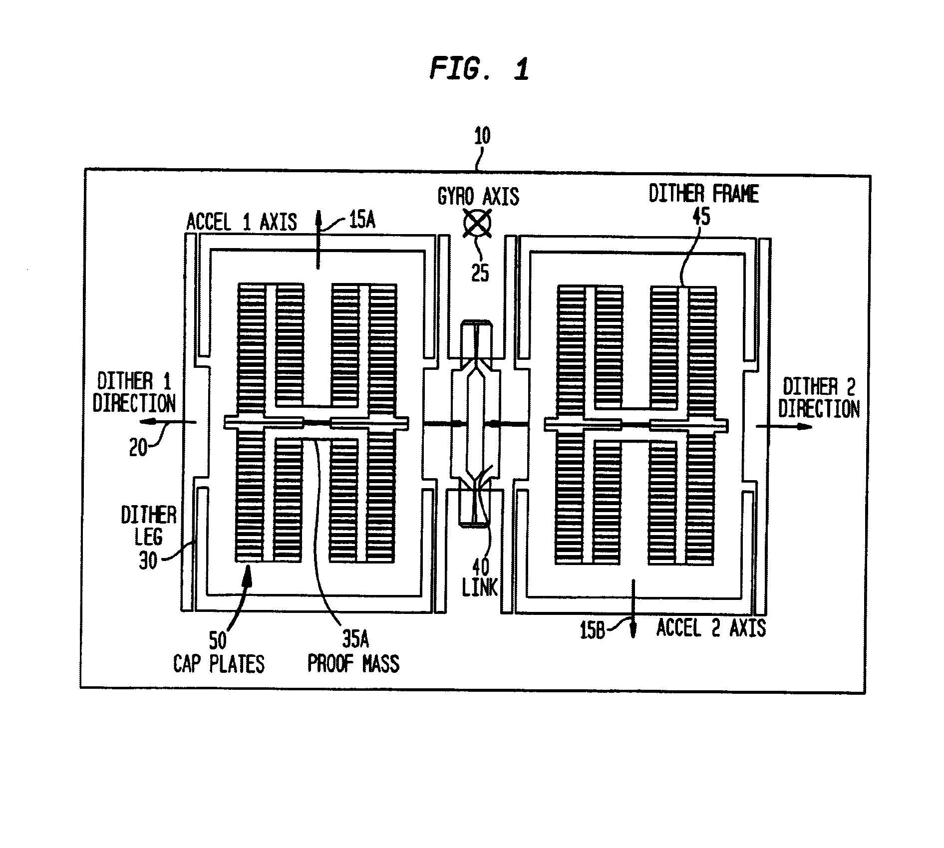
[0055]The present invention relates to an analog silicon version of L-3 Communications' existing vibrating beam, bulk etched, rate and acceleration sensor, which is a part of L-3 Communications' existing μIMU (micro Inertial Measurement Unit). Inertial Measurement units (IMUs) are critical to the operation of inertial navigation and guidance systems. Such sys...


PUM


Abstract

The present invention provides an apparatus and method for measuring the angular rotation of a moving body. The apparatus comprises an upper sensor layer, a lower handle layer substantially parallel to the sensor layer, at least one dither frame formed of the upper sensor layer, the frame having a dither axis disposed substantially parallel to the upper sensor layer and the lower handle layer. The apparatus further comprises a first accelerometer formed of the upper sensor layer and having a first force sensing axis perpendicular to the dither axis for producing a first output signal indicative of the acceleration of the moving body along the first force sensing axis, the first accelerometer having a proof mass and at least one flexure connecting the proof mass to the dither frame such that the proof mass can be electrically rotated perpendicular to the dither axis. The apparatus also comprises a second accelerometer formed of the upper sensor layer and having a second force sensing axis perpendicular to the dither axis for producing a second output signal indicative of the acceleration of the moving body along the second force sensing axis, the second accelerometer having a proof mass and at least one flexure connecting the proof mass to the dither frame such that the proof mass can be electrically rotated perpendicular to the dither axis. The dither frame and proof masses have electrodes on an insulating layer for operating the first and second accelerometers and the upper sensor layer has a rate axis perpendicular to each of the first and second force sensing axes and the dither axis, whereby the first and second output signals have a Coriolis component indicative of the angular rotation of the moving body about the rate axis.

Description

CROSS-REFERENCES TO RELATED APPLICATIONS[0001]This is a continuation-in-part of application Ser. No. 10 / 136,525, filed Apr. 29, 2002, now U.S. Pat. No. 6,701,786.BACKGROUND[0002]1. Technical Field of the Invention[0003]The present invention relates to an apparatus and methods for determining the acceleration and rate of angular rotation of a moving body, and in particular, one which is adapted to be formed, for example through micromachining, from a silicon substrate.[0004]2. Description of the Prior Art[0005]A variety of methods and systems are known for determining the acceleration and rate of angular rotation of a moving body. Such methods and systems have found their way in a diverse range of applications, one of which is military. However, the use of tactical grade inertia measuring units has been limited by their cost to high-priced systems such as military aircraft, missiles, and other special markets. The cost of inertia measuring units is dominated by the expensive discrete...

Claims


Application Information

Patent Timeline
Patent Type & Authority Patents(United States)
IPC IPC(8): G01P15/00G01C19/5719G01P15/125
CPCG01P15/125G01C19/5719
Inventor HULSING, II, RAND H.
Owner L 3 COMM CORP
Why Eureka
Try Eureka