Wind power fed network

a technology of wind power and network, applied in the direction of electric generator control, machine/engine, dynamo-electric converter control, etc., can solve the problems of inability to control the reactive power consumption of this type of generator cannot inherently generate reactive power, and the voltage variation is particularly considerabl

Inactive Publication Date: 2007-07-17
ABB POWER GRIDS SWITZERLAND AG
View PDF12 Cites 46 Cited by
  • Summary
  • Abstract
  • Description
  • Claims
  • Application Information

AI Technical Summary

Benefits of technology

[0022]It is an object of the invention to provide in an electric network having a power generating part that comprises at least one wind turbine with an electric generator of induction type, the use of a reactive power compensating means that can be directly connected even to voltages typical for transmission links, and the susceptance of which can be controlled without generation of harmonics.

Problems solved by technology

However, induction generators cannot inherently generate reactive power, and the reactive power needed for their operation is thus provided by phase capacitors coupled to the stator windings of the generator.
The reactive power consumption of this type of generators is not controllable but dependent on the active power and on the voltage of the generator.
These voltage variations are particularly considerable when the network is weak, i.e. has a low short circuit capacity.
In particular with increasing unit sizes of the windmills and with an increasing distance between the wind power plant and the grid, the voltage control at the point of common connection has been identified as a problem.
This of course means an undesirable loss of energy.
However, for example imperfections in the gearbox may be the cause of fluctuations even in higher frequency ranges, typically in the order of up to 8 Hz.
Although the induction generators of a fixed-speed windmill have some inherent damping, such torque fluctuations will, due the consequential fluctuations in the rotational speed of the induction generator, cause fluctuations in the outputted active power of the generator, and, due to the inherent characteristic of such a generator, also in the reactive power exchange with the power collection system, thereby affecting the voltage quality of the electric power grid.
This limits the options for connection of a TCR, which, because of the thyristors comprised therein, is usually not connected directly, i.e. without a coupling transformer, to voltages higher than 36 kV.

Method used


Image

  • Wind power fed network
  • Wind power fed network

Examples


Embodiment Construction

[0028]The following description relates both to electric network and to the use of a reactive power compensating means.

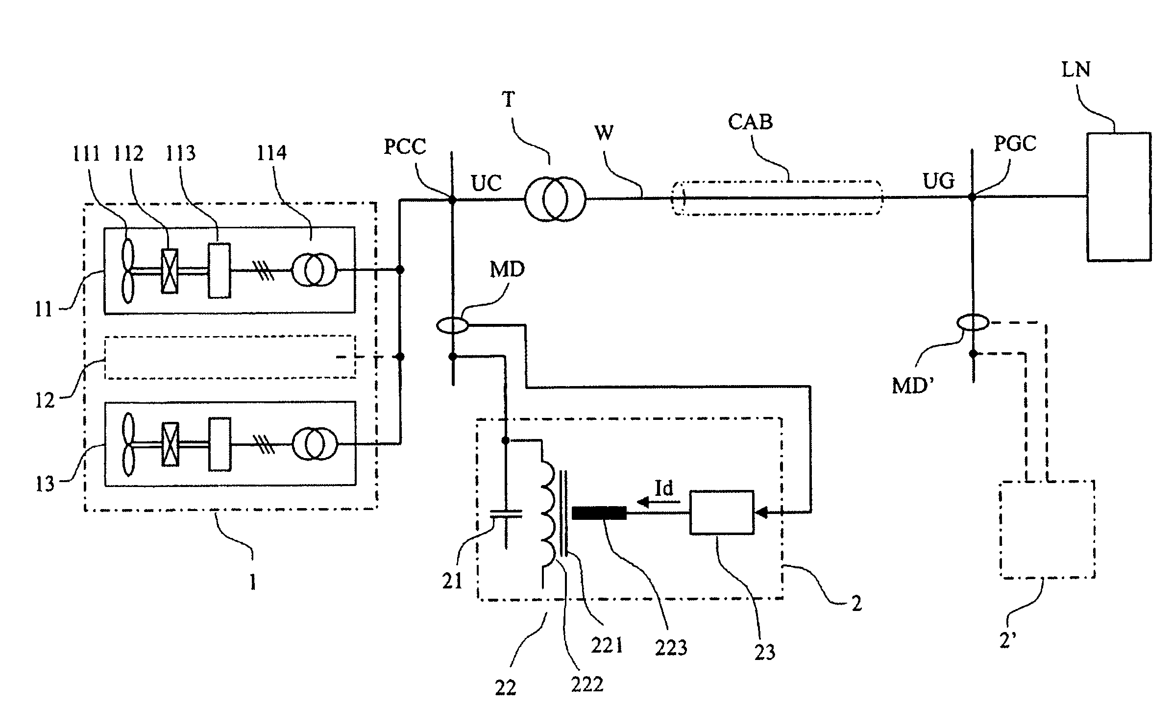
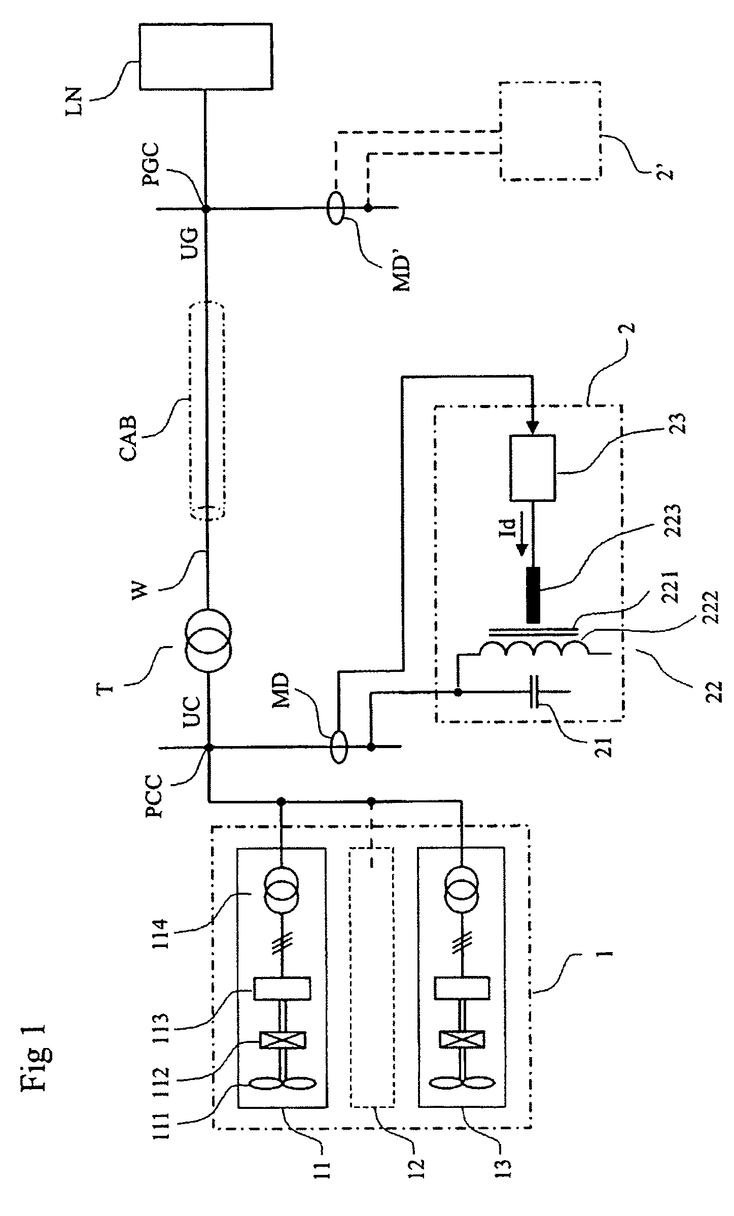
[0029]FIG. 1 shows a three-phase electric network for generation and transmission of electric power, having a power generating part 1, a point of common connection PCC for the power generating part, a transmission link, a load network LN, and a reactive power compensating means 2.

[0030]The active power generated by the power generating part is supplied to the load network via the transmission link, that is coupled between the point of common connection and a grid connection point PGC at the load network.

[0031]The transmission link comprises a high voltage step-up transformer T with its low voltage side coupled to the point of common connection, and its high voltage side coupled to a transmission line W. The transmission line is at least to a part embodied as a cable CAB.

[0032]The power generating part comprises one or more, typically a plurality, of windmills, of wh...


PUM


Abstract

An electric network for generation and transmission of electric power, including a power generating part, a point of common connection for the power generating part, a transmission link, a load network, and a reactive power compensator. The transmission link is coupled between the point of common connection and a grid connection point at the load network. The reactive power compensator is coupled to transmission link. The power generating part includes at least one wind turbine with an electric generator of induction type, coupled to the point of common connection. The reactive power compensator includes a capacitor bank and in parallel coupling to the capacitor bank a controllable inductor having a magnetic core, a main winding for alternating current, and a DC-control winding for direct current. The DC-control winding for control of the magnetic flux is set up by the main winding via orthogonal magnetization of the core.

Description

TECHNICAL FIELD[0001]The present invention relates to the use of a reactive power compensating means for compensation of reactive power in an electric network having a power generating part, a point of common connection for the power generating part, a transmission link, a load network, the transmission link coupled between the point of common connection and a grid connection point at the load network, wherein the reactive power compensating means is coupled to the transmission link.[0002]It also relates to an electric network for generation and transmission of electric power, having a power generating part, a point of common connection for the power generating part, a transmission link, a load network, and a reactive power compensating means, the transmission link coupled between the point of common connection and a grid connection point at the load network, and the reactive power compensating means coupled to the transmission link.BACKGROUND ART[0003]A general description of wind ...

Claims


Application Information

Patent Timeline
Patent Type & Authority Patents(United States)
IPC IPC(8): H02P9/00H02J3/18H02J3/38
CPCH02J3/1835Y02E40/30H02J2300/28H02J3/381Y02E10/76H02J3/50
Inventor ÄNGQUIST, LENNARTHALVARSSON, PERLILJESTRAND, LARSVALDEMARSSON, STEFANBENGTSSON, CLAESWONG, WILLIE
Owner ABB POWER GRIDS SWITZERLAND AG
Why Eureka
Try Eureka