Exhaust-heat recovery system for engine

a technology of exhaust and recovery system, which is applied in the direction of machines/engines, electric control, transportation and packaging, etc., can solve the problems of low temperature of exhaust, low small volume of exhaust, so as to increase the heat quantity of exhaust, increase the efficiency of temperature, and efficiently warmed

Inactive Publication Date: 2007-07-24
CALSONIC KANSEI CORP
View PDF18 Cites 48 Cited by
  • Summary
  • Abstract
  • Description
  • Claims
  • Application Information

AI Technical Summary

Benefits of technology

[0010]According to the present invention, since the engine controller controls incrementally the combustible components in the exhaust to be burned in the catalytic converter when the prescribed condition for heating is not satisfied, the combustion in the catalytic converter is promoted to increase the heat quantity of the exhaust as well as to increase efficiently the temperature of the heat-transfer medium to exchange heat with the exhaust in the exhaust heat exchanger.
[0011]Consequently, even when sufficient heat quantity of the exhaust from the engi...

Problems solved by technology

The system has a problem that the volume and temperature of the exhaust vary depending upon the magnitude of a load on the engine.
When the engine is idling (the vehicle is at rest but the engine is still in operation) in a cold period such as winter, the volume of th...

Method used


Image

  • Exhaust-heat recovery system for engine
  • Exhaust-heat recovery system for engine
  • Exhaust-heat recovery system for engine

Examples


Embodiment Construction

[0017]A first embodiment of the present invention will be described referring to FIGS. 1 to 3.

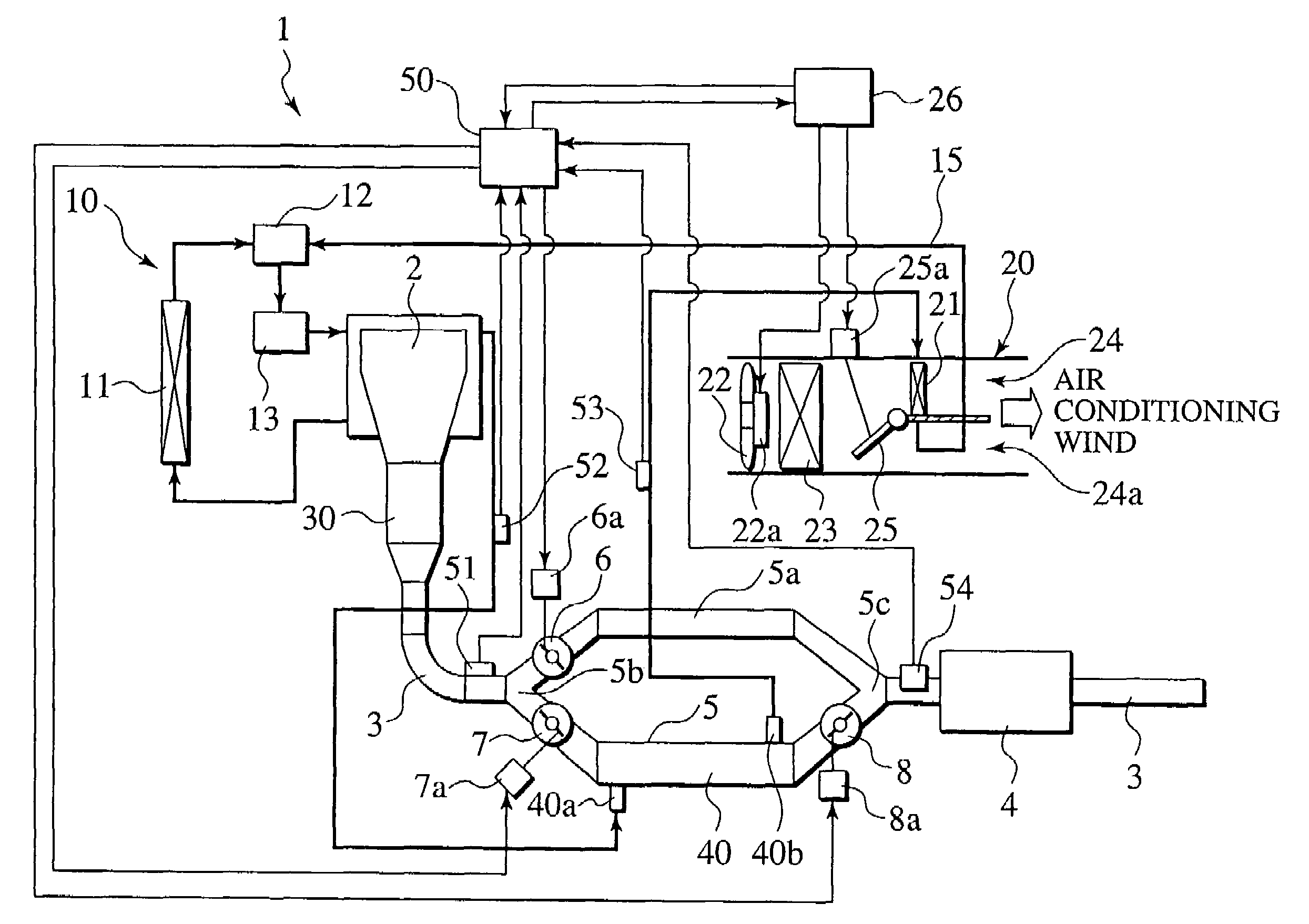
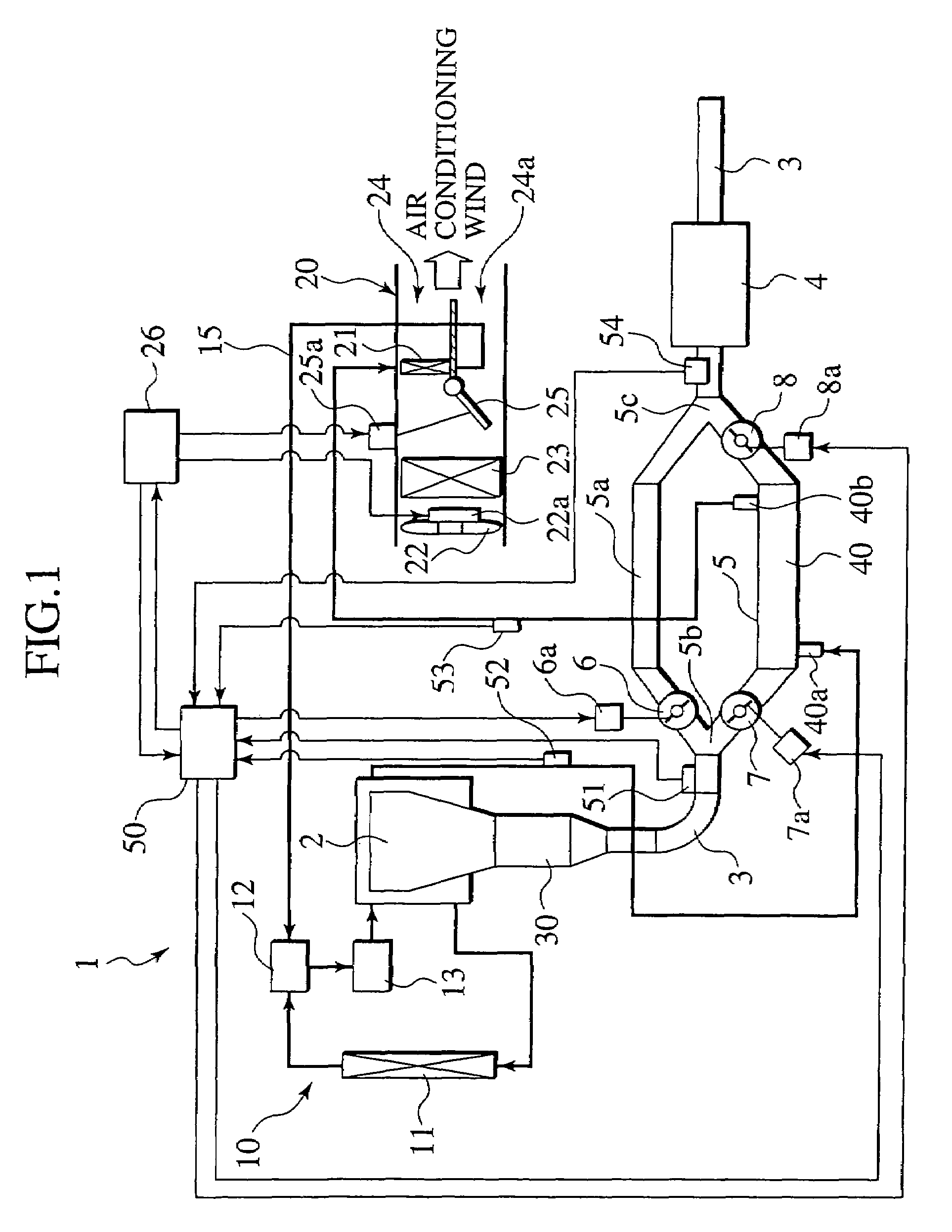
[0018]An exhaust-heat recovery system for an engine 1 includes, as shown in FIG. 1, an engine cooling system 10, an air conditioner 20, a catalytic converter 30, an exhaust heat exchanger 40 and an engine controller 50. The engine cooling system 10 cools an on-vehicle engine 2 by means of heat exchange with a coolant (a heat-transfer medium). The air conditioner 20 introduces a heated coolant of a heating medium circulation channel 15 into the interior of a heater core 21 (a heat exchanger for heating) and then generates a heating wind by means of heat exchange between an air conditioning wind and the heated coolant. The catalytic converter 30 burns combustible components in the exhaust through catalysis by passing the exhaust from the engine 2 in the interior thereof. The exhaust heat exchanger 40 causes the exhaust, which has passed through the catalytic converter 30, to exchange the heat...


PUM


Abstract

An exhaust-heat recovery system includes a catalytic converter, an exhaust heat exchanger, an air conditioner and an engine controller. The catalytic converter is such that exhaust discharged from an engine passes therethrough and combustible components in the exhaust are catalytically burned therein. The exhaust heat exchanger induces heat exchange between the exhaust having passed through the catalytic converter and a coolant having passed through the engine. The air conditioner generates a heating wind by means of the heat exchange between the coolant having passed through the exhaust heat exchanger and an air conditioning wind. The engine controller controls incrementally the combustible components in the exhaust to be burned in the catalytic converter when a prescribed heating condition is unsatisfied.

Description

CROSS REFERENCE TO RELATED APPLICATION[0001]This application claims benefit of priority under 35. U.S.C § 119 to Japanese Patent Application No. 2002-334882, filed on Nov. 19, 2002, the entire contents of which are incorporated by reference herein.BACKGROUND OF THE INVENTION[0002]1. Field of the Invention[0003]The present invention relates to an exhaust-heat recovery system for an engine in order to utilize exhaust heat for air conditioning, heating, etc. by means of efficient recovery thereof from the engine.[0004]2. Description of the Related Art[0005]There has been conventionally well known a system disclosed in JP 1-132415A, which utilizes exhaust heat from an engine for heating the interior of a vehicle. The system heats a coolant for the engine utilizing the exhaust heat and sends a heating wind into the interior of the vehicle by passing the heated coolant through a heat exchanger disposed along a warm-air duct.[0006]The system has a problem that the volume and temperature of...

Claims


Application Information

Patent Timeline
IPC IPC(8): F01N3/00F01N5/02B60H1/02B60H1/08F01N3/20F01N3/24F01N3/28F02D41/02F02G5/02
CPCB60H1/025F01N3/2882F01N5/02F02D41/029F02G5/02F01N2240/02F01N2410/00F01N2430/02F01N2430/06F01N2430/08F01P2060/08F01P2060/16Y02T10/16Y02T10/166Y02T10/12
Inventor HARA, JUNICHIRO
Owner CALSONIC KANSEI CORP
Why Eureka
Try Eureka