
Contamination barrier with expandable lamellas

a contamination barrier and expandable lamella technology, applied in the field of lithographic equipment, can solve the problems of significant heating of the lamella, xe gas absorbing euv radiation, and support structure, and achieve the effect of minimizing the deformation of the lamella

Inactive Publication Date: 2007-07-24
ASML NETHERLANDS BV
View PDF18 Cites 18 Cited by
  • Summary
  • Abstract
  • Description
  • Claims
  • Application Information

AI Technical Summary

Benefits of technology

[0009]Therefore, it is an aspect of the present invention to provide a contamination barrier in which disadvantageous deformation of lamellas is minimized.
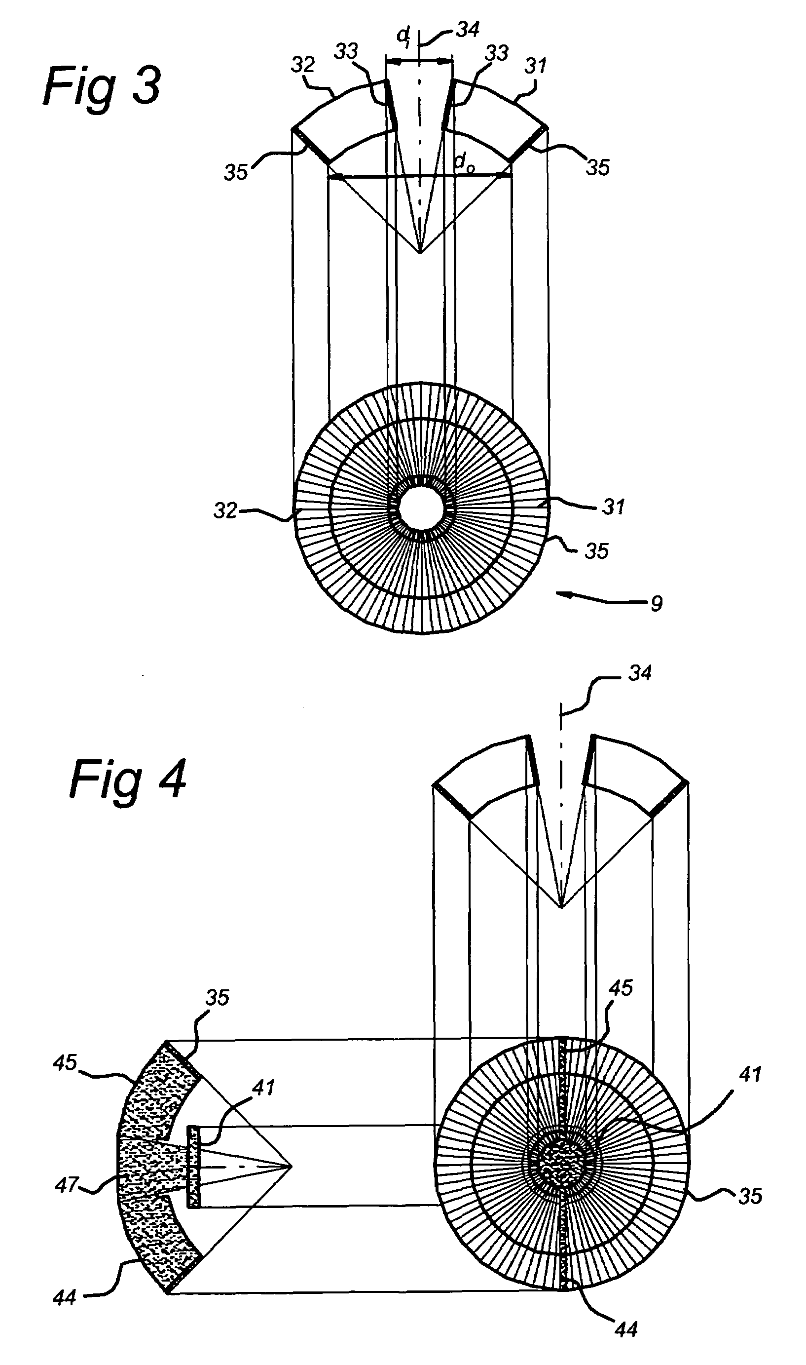
[0010]It is another aspect of embodiments of the present invention to provide a foil trap for a lithographic projection apparatus. The foil trap forms an open structure to let radiation coming from, for example, an EUV source, pass unhindered. The foil trap comprises lamellas arranged to capture debris particles coming from the radiation source. The lamellas are extending in a radial direction from a foil trap axis. In order to prevent mechanical stress, the lamellas are slidably connected in grooves of one or both of the rings. In this way, the lamellas can expand easily and mechanical stress is avoided, so that there is no deformation of the lamellas. At least one of the outer ends of the lamellas is thermally connected to a ring. This ring may be cooled by a cooling system. In a preferred embodiment, the foil trap comprises a shield to protect the inner ring from being hit by the EUV beam.

Problems solved by technology

A drawback of having such a rather high Xe pressure is that Xe gas absorbs EUV radiation.
This results in significant heating of the lamellas and a supporting structure which supports the lamellas.
Since optical transmission is very important in a lithographic projection apparatus, mechanical deformation is not allowed.

Method used


Image

  • Contamination barrier with expandable lamellas
  • Contamination barrier with expandable lamellas
  • Contamination barrier with expandable lamellas

Examples


Embodiment Construction

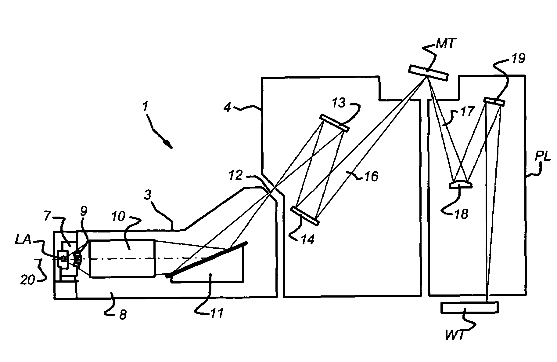
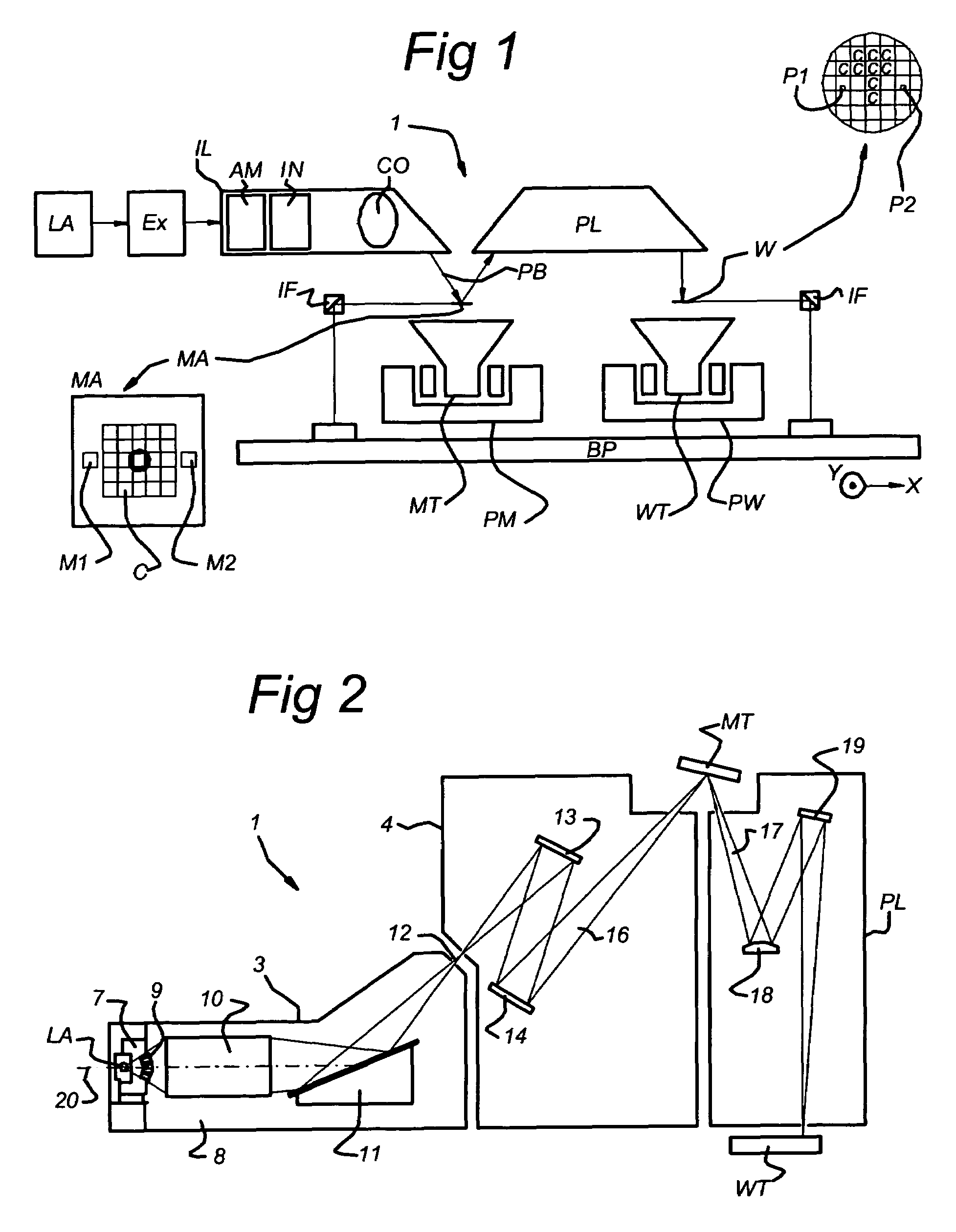
[0056]FIG. 1 schematically depicts a lithographic projection apparatus 1 according to a particular embodiment of the invention. The apparatus comprises: a radiation system Ex, IL, for supplying a projection beam PB of radiation (e.g. EUV radiation) with a wavelength of 11–14 nm. In this particular case, the radiation system also comprises a radiation source LA; a first object table (mask table) MT provided with a mask holder for holding a mask MA (e.g. a reticle), and connected to a first positioning device PM for accurately positioning the mask with respect to item PL; a second object table (substrate table) WT provided with a substrate holder for holding a substrate W (e.g. a resist coated silicon wafer), and connected to a second positioning device PW for accurately positioning the substrate with respect to item PL; and a projection system (“lens”) PL for imaging an irradiated portion of the mask MA onto a target portion C (e.g. comprising one or more dies) of the substrate W. Th...


PUM

PropertyMeasurementUnit
wavelengthaaaaaaaaaa
pressureaaaaaaaaaa

Abstract

A contamination barrier that passes through radiation from a radiation source and captures debris coming from the radiation source is disclosed. The contamination barrier includes an inner ring, an outer ring, and a plurality of lamellas. The lamellas extend in a radial direction from a main axis, and each of the lamellas is positioned in a respective plane that include the main axis. At least one outer end of each of the lamellas is slidably connected to at least one of the inner and outer ring.

Description

CROSS-REFERENCE TO RELATED APPLICATIONS[0001]This application is based on and claims the benefit of priority from European Patent Application No. 02080454.8, filed Dec. 23, 2002, and European Patent Application No. 03075086.3, filed Jan. 13, 2003, the contents of which are both incorporated herein by reference.BACKGROUND OF THE INVENTION[0002]1. Field of the Invention[0003]The invention relates generally to a lithographic apparatus, and more specifically to a contamination barrier for passing through radiation from a radiation source and for capturing debris coming from the radiation source.[0004]2. Description of Related Art[0005]A contamination barrier for a lithographic apparatus is known from, for example, the international patent application WO 02 / 054153. The contamination barrier is normally positioned in a wall between two vacuum chambers of a radiation system of a lithographic projection apparatus.[0006]In a lithographic projection apparatus, the size of features that can be...

Claims


Application Information

Patent Timeline
Patent Type & Authority Patents(United States)
IPC IPC(8): G21G5/00G21K1/00G03F7/20G21K3/00G21K5/00G21K5/02H01L21/027
CPCB82Y10/00G03F7/70916G03F7/70166G03F7/20
Inventor BAKKER, LEVINUS PIETERDIERICHS, MARCEL MATHIJS THEODORE MARIEFRERIKS, JOHANNES MARIASCHUURMANS, FRANK JEROEN PIETERVIJFVINKEL, JAKOBBOX, WILHELMUS JOSEPHUS
Owner ASML NETHERLANDS BV
Learn More