Optical fiber for Raman amplification, optical fiber coil, Raman amplifier, and optical communication system

a technology of optical fiber and amplifier, applied in the field of optical fiber for raman amplification, optical fiber coil, raman amplifier, and optical communication system, can solve the problems of poor amplification efficiency of conventional raman amplifier, degraded amplification efficiency, and insufficient application of raman amplifier

Active Publication Date: 2007-07-24
FURUKAWA ELECTRIC CO LTD
View PDF8 Cites 17 Cited by
  • Summary
  • Abstract
  • Description
  • Claims
  • Application Information

AI Technical Summary

Benefits of technology

[0045]In the optical fiber for Raman amplification, a chromatic dispersion value is from −70 ps / nm / km to −30 ps / nm / km at a wavelength of 1,550 nm, a Raman gain efficiency is 5 (W×km)−1 or more with a pumping light of 1,450 nm, a nonlinear coefficient is 5.0×10⁻⁹ W−1 or less at a wavelength of 1,550 nm, a zero-dispersion wavelength λ0 is neither at a wavelength of the signal light nor at a wavelength of the pumping light, and a cut-off wavelength λc is equal to or less than a wavelength of the pumping light.
[0014]An optical fiber for Raman amplification according to one aspect of the present invention includes a glass part and a coating surrounding the glass part. A chromatic dispersion at a wavelength of 1,550 nm is in a range between −70 ps / nm / km and −30 ps / nm / km. Raman gain efficiency with a pumping light of 1,450 nm is equal to or more than 5 (W×km)−1. Nonlinear coefficient at a wavelength of 1,550 nm is equal to or less than 5.0×10⁻⁹ W−1. Zero-dispersion wavelength is neither at a wavelength of the signal light nor at a wavelength of the pumping light. Cut-off wavelength is equal to or less than a wavelength of the pumping light.
[0140]Moreover, according to the present invention, it is possible to use pumping light energy efficiently for a signal light having a wavelength equal to or more than 1460 nm.
[0003]The present invention relates to an optical fiber for Raman amplification that amplifies a signal light with a pumping light, an optical fiber coil formed by winding the optical fiber for Raman amplification around a bobbin, a Raman amplifier including the optical fiber for Raman amplification, and an optical communication system including the Raman amplifier.
[0055]In the optical fiber for Raman amplification, the Raman effective area Aeff,R is minimized in a certain chromatic dispersion region. Thus, with the same core, the Raman gain efficiency (gR / Aeff,R) is maximized when the Raman effective area Aeff,R is minimized. On the other hand, the nonlinear coefficient (n2 / Aeff,s) is maximum in the chromatic dispersion region where the effective area of the signal light Aeff,s is minimum.
[0047]The optical fiber for Raman amplification is able to increase the Raman gain efficiency while suppressing the nonlinear coefficient, because the chromatic dispersion value at a wavelength of 1,550 nm is set as described above. Furthermore, the optical fiber for Raman amplification,is able to perform Raman amplification on a signal light in a highly efficient manner, because the Raman gain efficiency with a pumping light of 1,450 nm is set as described above. Moreover, the optical fiber for Raman amplification is able to suppress distortion of signal light waveforms caused by self-phase modulation and cross-phase modulation, because the nonlinear coefficient at a wavelength of 1,550 nm is set as described above. Likewise, distortion of signal light waveforms and pumping light waveforms caused by four-wave mixing is suppressed, because the zero-dispersion wavelength λ0 is not at the signal light wavelength and the pumping light wavelength as described above. Further, because the cut-off wavelength λc is set as described above, the pumping light can be propagated in a single mode, so that pumping light energy is effectively used.
[0047]The optical fiber for Raman amplification is able to increase the Raman gain efficiency while suppressing the nonlinear coefficient, because the chromatic dispersion value at a wavelength of 1,550 nm is set as described above. Furthermore, the optical fiber for Raman amplification,is able to perform Raman amplification on a signal light in a highly efficient manner, because the Raman gain efficiency with a pumping light of 1,450 nm is set as described above. Moreover, the optical fiber for Raman amplification is able to suppress distortion of signal light waveforms caused by self-phase modulation and cross-phase modulation, because the nonlinear coefficient at a wavelength of 1,550 nm is set as described above. Likewise, distortion of signal light waveforms and pumping light waveforms caused by four-wave mixing is suppressed, because the zero-dispersion wavelength λ0 is not at the signal light wavelength and the pumping light wavelength as described above. Further, because the cut-off wavelength λc is set as described above, the pumping light can be propagated in a single mode, so that pumping light energy is effectively used.
[0148]Moreover, according to the present invention, it is possible to perform a long-haul transmission of a signal light, and to suppress degradation of waveform of the signal light due to the nonlinear optical phenomena and the chromatic dispersion.
[0049]Firstly, the Raman gain efficiency (gR / Aeff,R) of the optical fiber for Raman amplification is described. A Raman gain coefficient gR is determined by core composition of the optical fiber (first core and second core). A Raman effective area Aeff,R changes depending on the chromatic dispersion value, even if the core composition is the same. The Raman effective area Aeff,R is determined by an overlap of a pumping light and a signal light in the direction of the diameter of the optical fiber, and is obtained from Equation (4) according to “European Conference on Optical Communication (ECOC) 2002, Symposium 3.3 (2002)”
[0047]The optical fiber for Raman amplification is able to increase the Raman gain efficiency while suppressing the nonlinear coefficient, because the chromatic dispersion value at a wavelength of 1,550 nm is set as described above. Furthermore, the optical fiber for Raman amplification,is able to perform Raman amplification on a signal light in a highly efficient manner, because the Raman gain efficiency with a pumping light of 1,450 nm is set as described above. Moreover, the optical fiber for Raman amplification is able to suppress distortion of signal light waveforms caused by self-phase modulation and cross-phase modulation, because the nonlinear coefficient at a wavelength of 1,550 nm is set as described above. Likewise, distortion of signal light waveforms and pumping light waveforms caused by four-wave mixing is suppressed, because the zero-dispersion wavelength λ0 is not at the signal light wavelength and the pumping light wavelength as described above. Further, because the cut-off wavelength λc is set as described above, the pumping light can be propagated in a single mode, so that pumping light energy is effectively used.
[0056]Furthermore, the chromatic dispersion region in which the effective area Aeff,p of the pumping light is minimum, and the chromatic dispersion region in which the effective area Aeff,s of the signal light is minimum are different, and the Raman effective area Aeff,R is obtained by Equation (5). Therefore, in an appropriate chromatic dispersion region in which the effective area Aeff,p of the pumping light is minimum, it is possible to reduce the nonlinear coefficient (n2 / Aeff,s) and increase the Raman gain efficiency (gR / Aeff,R).
[0148]Moreover, according to the present invention, it is possible to perform a long-haul transmission of a signal light, and to suppress degradation of waveform of the signal light due to the nonlinear optical phenomena and the chromatic dispersion.
[0045]In the optical fiber for Raman amplification, a chromatic dispersion value is from −70 ps / nm / km to −30 ps / nm / km at a wavelength of 1,550 nm, a Raman gain efficiency is 5 (W×km)−1 or more with a pumping light of 1,450 nm, a nonlinear coefficient is 5.0×10⁻⁹ W−1 or less at a wavelength of 1,550 nm, a zero-dispersion wavelength λ0 is neither at a wavelength of the signal light nor at a wavelength of the pumping light, and a cut-off wavelength λc is equal to or less than a wavelength of the pumping light.
[0045]In the optical fiber for Raman amplification, a chromatic dispersion value is from −70 ps / nm / km to −30 ps / nm / km at a wavelength of 1,550 nm, a Raman gain efficiency is 5 (W×km)−1 or more with a pumping light of 1,450 nm, a nonlinear coefficient is 5.0×10⁻⁹ W−1 or less at a wavelength of 1,550 nm, a zero-dispersion wavelength λ0 is neither at a wavelength of the signal light nor at a wavelength of the pumping light, and a cut-off wavelength λc is equal to or less than a wavelength of the pumping light.
[0139]Furthermore, according to the present invention, it is possible to suppress degradation of waveform of a signal light an a pumping light caused by effect of four-wave mixing when amplifying a signal light in a wavelength band equal to or more than 1460 nm and equal to or less than 1675 nm.

Problems solved by technology

Currently, the Raman amplifier is not widely applied to the C band or the L band because conventional Raman amplifier is poor in amplification efficiency compared to the EDFA.
However, at the same time, amplification efficiency degrades, making a trade off between these factors.
Generally, nonlinear effects in optical fibers degrade transmission quality of WDM signals in many cases.
In the FWM, a noise light that is similar to amplified spontaneous emission (ASE) is input to a detector with the signal light, thereby generating an intensity noise due to a random interference.
Due to a combination of a dispersion of a transmission line and a temporal change of the phase shift (a change in instantaneous frequency), a waveform of the intensity modulation signal is distorted, resulting in an increased bit error rate.
For example, the FWM efficiency is low as long as the phase matching is not achieved.

Method used


Image

  • Optical fiber for Raman amplification, optical fiber coil, Raman amplifier, and optical communication system
  • Optical fiber for Raman amplification, optical fiber coil, Raman amplifier, and optical communication system
  • Optical fiber for Raman amplification, optical fiber coil, Raman amplifier, and optical communication system

Examples


Embodiment Construction

[0038]Exemplary embodiments of the present invention will be described below in detail with reference to the accompanying drawings. In the following description, common components are denoted by the same reference numerals and overlapping descriptions are omitted to avoid redundant explanations. The diagrams are not to the scale.

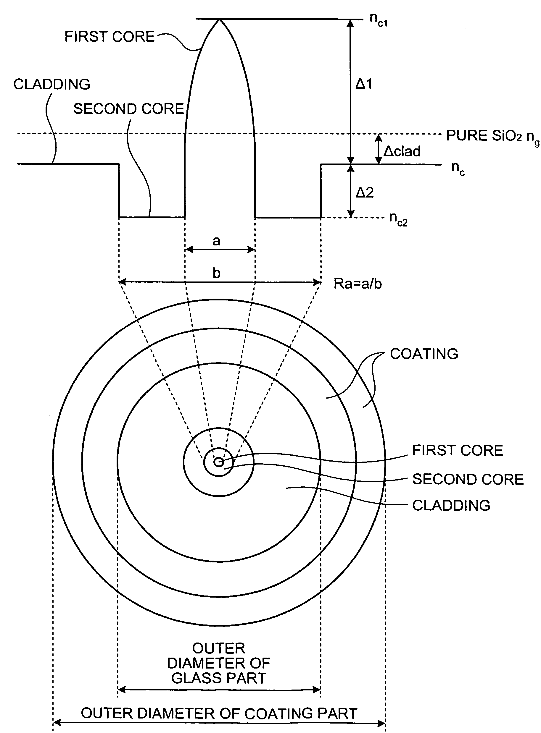
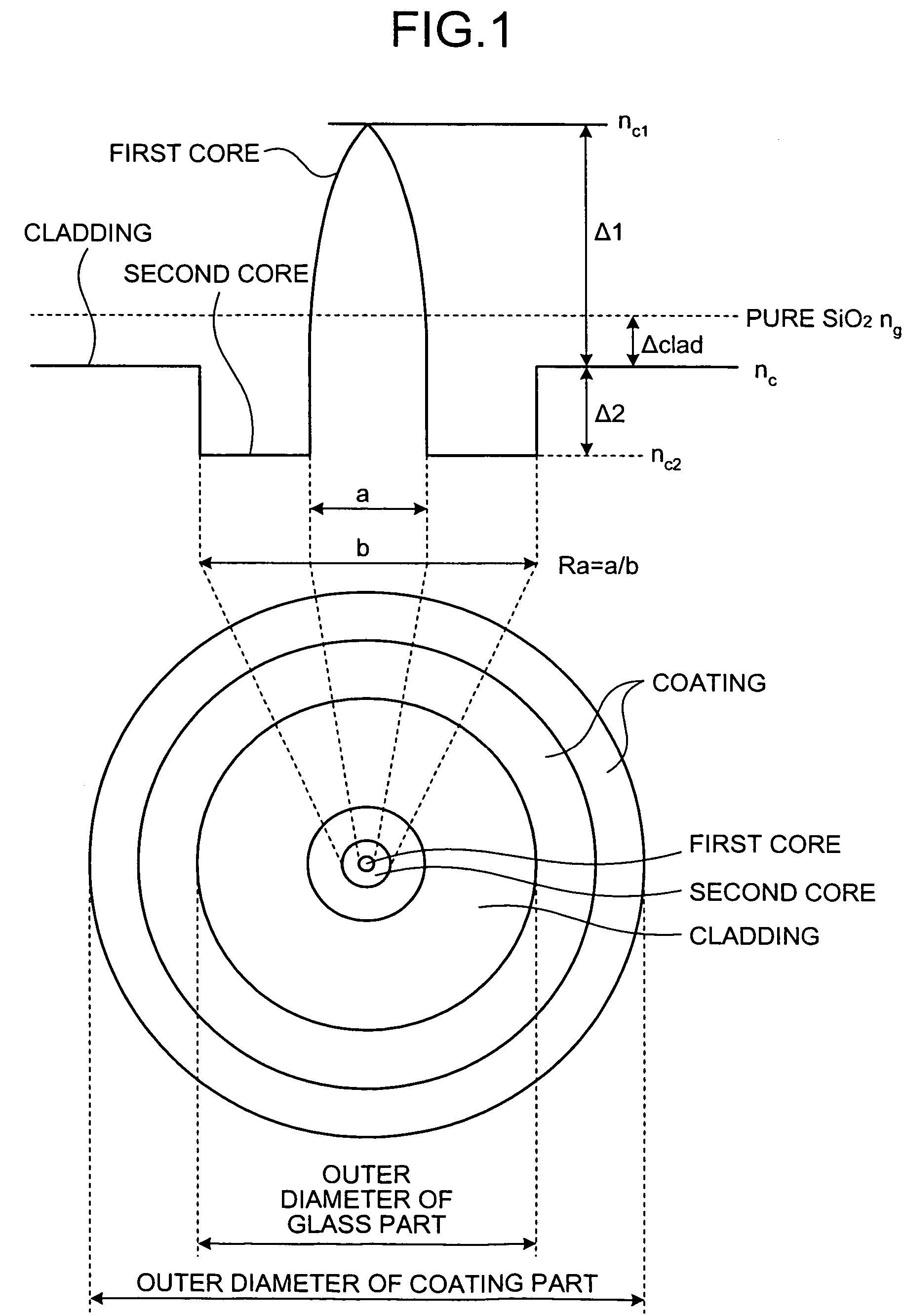
[0039]FIG. 1 is a schematic for illustrating a refractive index profile and a cross section of an optical fiber for Raman amplification according to the present invention.

[0040]The optical fiber includes a glass part substantially made of silicon dioxide (SiO2) and a coating surrounding the glass part. The glass part includes a first core having a diameter a, a second core that surrounds the first core and has a diameter b and a refractive index smaller than that of the first core, and a cladding that surrounds the second core and has a refractive index smaller than that of the first core and larger than that of the second core. The outer circumference of th...


PUM

PropertyMeasurementUnit
wavelengthaaaaaaaaaa
diameteraaaaaaaaaa
diameteraaaaaaaaaa

Abstract

An optical fiber for Raman amplification amplifies a signal light with a pumping light. A chromatic dispersion at a wavelength of 1,550 nm is in a range between −70 ps / nm / km and −30 ps / nm / km. Raman gain efficiency with a pumping light of 1,450 nm is equal to or more than 5 (W×km)−1. Nonlinear coefficient at the wavelength of 1,550 nm is equal to or less than 5.0×10⁻⁹ W−1. Zero-dispersion wavelength is neither at a wavelength of the signal light nor at a wavelength of the pumping light. Cut-off wavelength is equal to or less than the wavelength of the pumping light.

Description

CROSS-REFERENCE TO RELATED APPLICATIONS[0001]This application is a continuation of PCT / JP2005 / 007161 filed on Apr. 13, 2005, the entire content of which are incorporated herein by reference.BACKGROUND OF THE INVENTION[0002]1. Field of the Invention[0003]The present invention relates to an optical fiber for Raman amplification that amplifies a signal light with a pumping light, an optical fiber coil formed by winding the optical fiber for Raman amplification around a bobbin, a Raman amplifier including the optical fiber for Raman amplification, and an optical communication system including the Raman amplifier.[0004]2. Description of the Related Art[0005]Recently, broadband Internet services are steadily spread, from which it is clear that-there is a need for a backbone network having even larger capacity. For the past 10 years, a wavelength division multiplexing (WDM) has become a mainstream technology for increasing a capacity of an optical-fiber communication system. Signal wavelen...

Claims


Application Information

Patent Timeline
Patent Type & Authority Patents(United States)
IPC IPC(8): H01S4/00H04B10/12G02B6/02G02F1/35H01S3/067H01S3/094H01S3/30
CPCG02B6/02242G02B6/02252G02B6/0281G02B6/03627H01S3/06716H01S3/06758H01S3/094003H01S3/302G02B6/02028H01S3/06725H01S3/06729H01S3/06766H01S3/0677H01S3/06775
Inventor TANIGUCHI, YUKIEMORI, YOSHIHIROSUGIZAKI, RYUICHIOGURI, ATSUSHIYAGI, TAKESHI
Owner FURUKAWA ELECTRIC CO LTD
Why Eureka
Try Eureka