Heating device for vehicle

a heating device and vehicle technology, applied in the field of vehicle heating devices, can solve the problems of deteriorating the heating capacity of the air conditioner, affecting the efficiency of the heating device, and the inability of the engine to supply sufficient heat, so as to improve the mounting performance reduce the energy density of the heating device, and increase the optical path width of the infrared rays

Inactive Publication Date: 2007-07-24
DENSO CORP
View PDF12 Cites 16 Cited by
  • Summary
  • Abstract
  • Description
  • Claims
  • Application Information

AI Technical Summary

Benefits of technology

[0010]Therefore, the heat-radiating part of the heating device can be compacted, thus improving a mounting performance thereof in the vehicle. The radiation heat (infrared rays) having been converged to become parallel rays will be reflected toward the heating object by the second light-distributing unit which slantways intersects the infrared rays, without being directly thrown at the heating object. Thus, the optical path width of the infrared rays is enlarged, and the energy density thereof is reduced. Therefore, a passenger in the passenger compartment can be provided with a safe heating, even when being directly heated.
[0011]Moreover, in this case, the radiation heat is converged to have the substantially single irradiation direction. Therefore, the radiation heat can be efficiently transferred even when the radiation-heat generating unit is constructed of a compacted halogen lamp or the like having a small power, while the irradiation area of the heating object is enlarged due to a diffusion of the irradiation in an appropriate range so that the comfort of the passenger can be bettered.

Problems solved by technology

In this case, heating of air introduced into the passenger compartment may be insufficient before the temperature of cooling water in the engine is heightened, thus deteriorating a heating capacity of the air conditioner.
For example, in a hybrid vehicle or a vehicle having a high-efficiency traveling engine, it is difficult for engine cooling water to supply a sufficient heat amount to a heating operation of the air conditioner.
However, in this case, the home-used heating device (halogen heater) is too big when being mounted in the vehicle.
On the other hand, if the halogen heater is small-sized, the density of the infrared rays from the halogen heater will be heightened to be dangerous.
Because the power of the halogen lamp which is mounted in the vehicle is to be restricted, a sufficient heating sense cannot be provided for the passenger if the irradiation range of the halogen lamp is enlarged.

Method used


Image

  • Heating device for vehicle
  • Heating device for vehicle
  • Heating device for vehicle

Examples


first embodiment

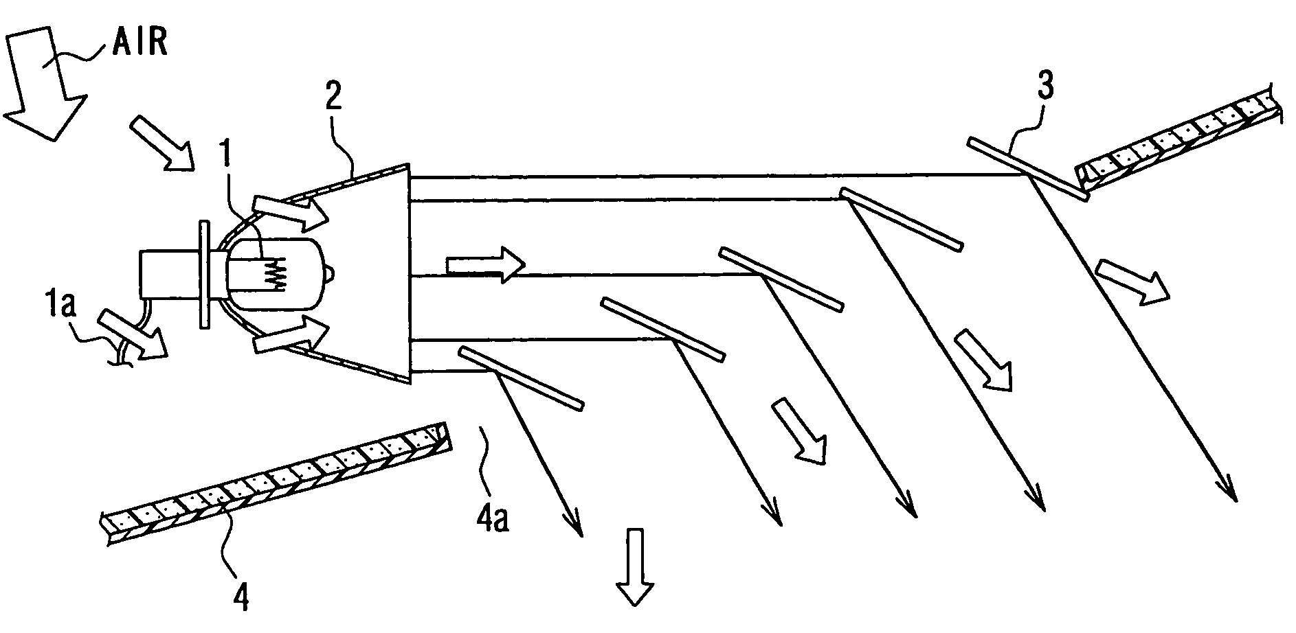
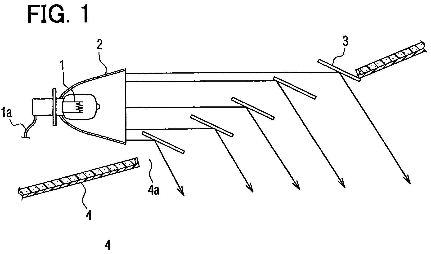
[0017]A heating device for a vehicle according to a first embodiment of the present invention will be described with reference to FIG. 1. The heating device is suitably used to heat at least one heating object (e.g., passenger feet) in a passenger compartment of the vehicle by radiation heat.

[0018]As shown in FIG. 1, a radiation-heat irradiating port 4a can be formed at a lower portion of an instrument panel 4 of the vehicle and face the passenger feet. A first light-distributing unit 2 (e.g., reflector) is disposed inside the instrument panel 4. A radiation-heat generating unit 1 (e.g., halogen lamp or infrared lamp) is arranged at the substantial center of the reflector 2. The halogen lamp 1, for example, is power-supplied through a lead line 1ato radiate infrared rays (radiation heat). The infrared rays emitted by the halogen lamp 1 are reflected and converged by the reflector 2 (having parabolic cross section, for example), to have a substantial single irradiation direction. Tha...

second embodiment

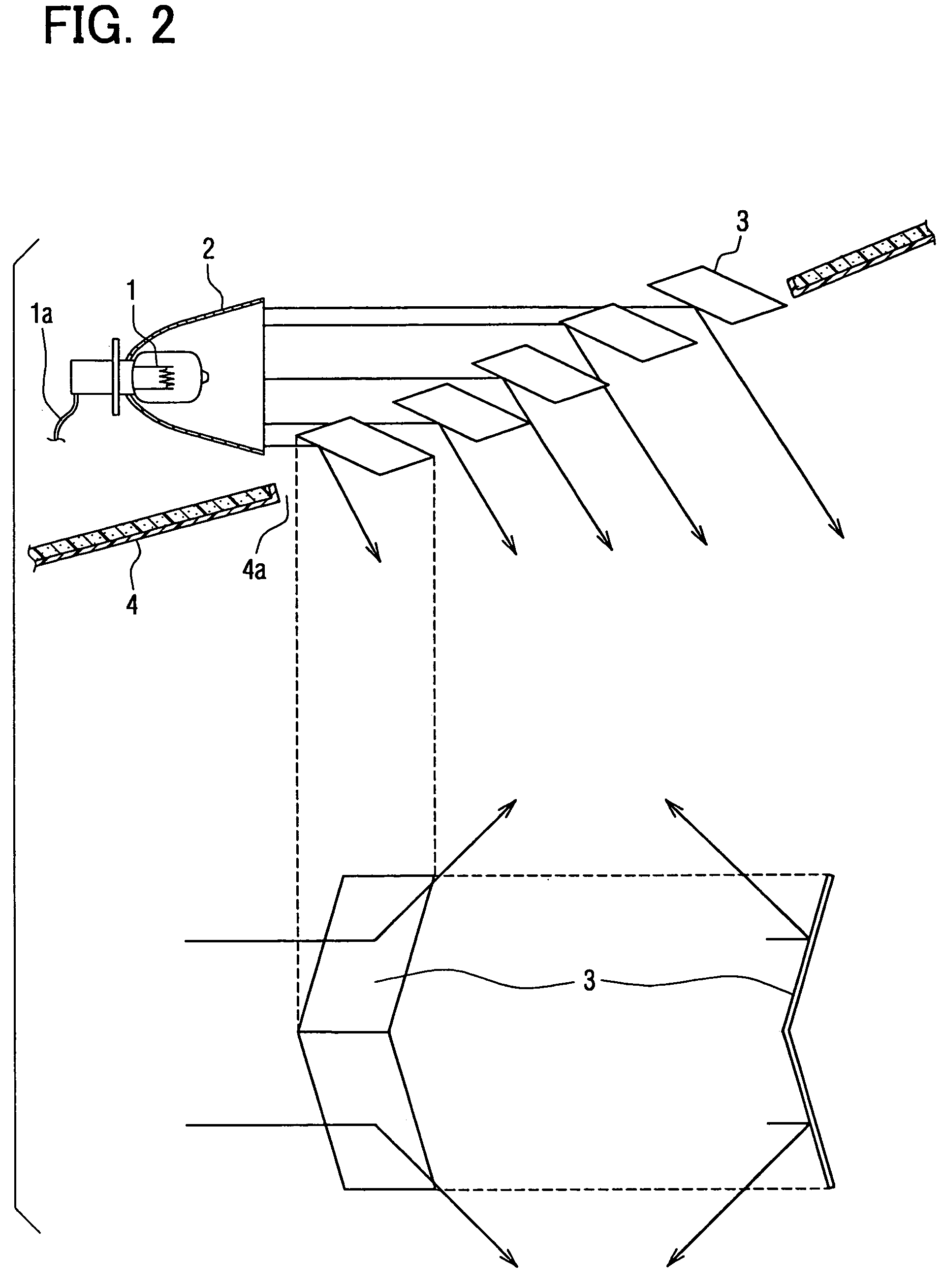
[0032]According to a second embodiment of the present invention, each of the reflectors 3 is constructed of a bent plate to have multiple reflection surfaces with respect to the radiation heat (infrared rays) emitted by the radiation-heat generating unit 1, so that multiple heating objects can be irradiated with the infrared rays. For example, referring to FIG. 2, each of the reflectors 3 is constructed of a plate which is bent at the substantial center thereof to have a substantial ‘<’ shape. Thus, the infrared rays from the heat-radiating portion of the heating device can be reflected to have two irradiation directions. Therefore, for example, the two feet of the passenger can be efficiently heated.

third embodiment

[0033]According to a third embodiment of the present invention, referring to FIG. 3, reflection angles of the reflectors 3 can be adjusted by an angle adjusting apparatus 5. Thus, the irradiation position of the infrared rays can be preferably changed by the passenger. The adjustment of the reflection angle can be manual or motor-driven.

[0034]A swing device 50 can be provided to swing the reflectors 3. Thus, the irradiation position of the infrared rays can be adjusted by a swinging of the plate-shaped reflectors 3 to enlarge the irradiation range thereof, while the infrared rays can be converged to some extent to provide a sufficient heating sense for the passenger. The reflector 3 can be swung in one direction (e.g., right-left direction or front-rear direction) or in two directions (e.g., right-left direction and front-rear direction).


PUM


Abstract

A heating device for a vehicle is provided with a radiation-heat generating unit for generating radiation heat, a first light-distributing unit for converting irradiation directions of the radiation heat into a substantial single irradiation direction, and a second light-distributing unit for distributing the radiation heat to at least one heating object in a passenger compartment of the vehicle. The second light-distributing unit slantways intersects the radiation heat which has the substantial single irradiation direction converted by the first light-distributing unit.

Description

CROSS REFERENCE TO RELATED APPLICATION[0001]This application is based on Japanese Patent Applications No. 2005-195539 filed on Jul. 4, 2005 and No. 2004-282271 filed on Sep. 28, 2004, the disclosure of which is incorporated herein by reference.FIELD OF THE INVENTION[0002]The present invention relates to a heating device for a vehicle. The heating device is suitably used for a heating in a passenger compartment of the vehicle by radiation heat, which is generated by a halogen lamp, an infrared lamp or the like.BACKGROUND OF THE INVENTION[0003]Generally, in an air conditioner for a vehicle, cooling water which cools an engine of the vehicle to become warm water is circulated through a heating heat exchanger. In the heating heat exchanger, warm water is used as a heat source to heat air, which will be introduced into a passenger compartment of the vehicle to temperature-condition it. In this case, heating of air introduced into the passenger compartment may be insufficient before the t...

Claims


Application Information

Patent Timeline
Patent Type & Authority Patents(United States)
IPC IPC(8): F21V7/00B60L1/02B60H1/03F24F1/00
CPCB60H1/22F24C7/065F24C15/30
Inventor MISUMI, HARUKIMATSUOKA, AKIO
Owner DENSO CORP
Why Eureka
Try Eureka