Solenoid-type fuel injector assembly having stabilized ferritic stainless steel components

a technology of ferritic stainless steel and fuel injector, which is applied in the direction of valve operating means/release devices, machines/engines, mechanical apparatus, etc., can solve the problems of increasing corrosion, affecting the stability of fuel injectors, so as to achieve the desired structural and mechanical properties, reduce the susceptibility of solenoid-type, and strengthen the soft magnetic properties

Active Publication Date: 2007-08-07
DELPHI TECH IP LTD
View PDF57 Cites 24 Cited by
  • Summary
  • Abstract
  • Description
  • Claims
  • Application Information

AI Technical Summary

Benefits of technology

[0012]Briefly described, the present invention is directed to a solenoid-type fuel injector assembly having at least one component formed of stabilized, solenoid quality ferritic stainless steel. In a preferred embodiment, an austenitic fuel tube is laser-welded to an injector body formed of the subject material, preferably a free-machining formulation thereof, comprising from about 10% to about 35% chromium, and at least one stabilizing element selected from the group consisting of titanium and columbium. Preferably, the

Problems solved by technology

A slipover injection molded plastic sleeve typically is employed to cover the weld sites; however, this can enhance corrosion at the covered weld sites by fostering an oxygen depletion condition.
Because of the high temperatures inherent in any laser welding process, non-stabilized ferritic stainless steel components and the like used in the production of solenoid-type fuel injectors can incur a deleterious metallurgical effect known as sensitization.
Non-stabilized ferritic stainless steel grades typically used in conventional solenoid-type fuel injectors incur metal sensitization upon being welded, and are thus rendered susceptible to intergranular corrosive atta

Method used


Image

  • Solenoid-type fuel injector assembly having stabilized ferritic stainless steel components
  • Solenoid-type fuel injector assembly having stabilized ferritic stainless steel components

Examples


Embodiment Construction

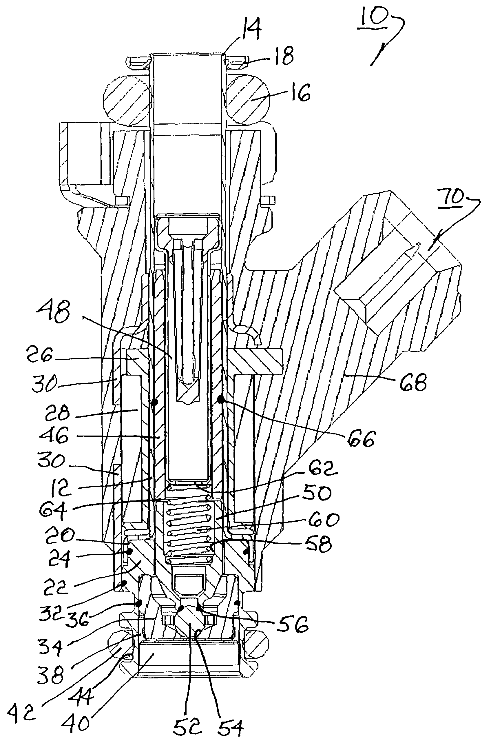
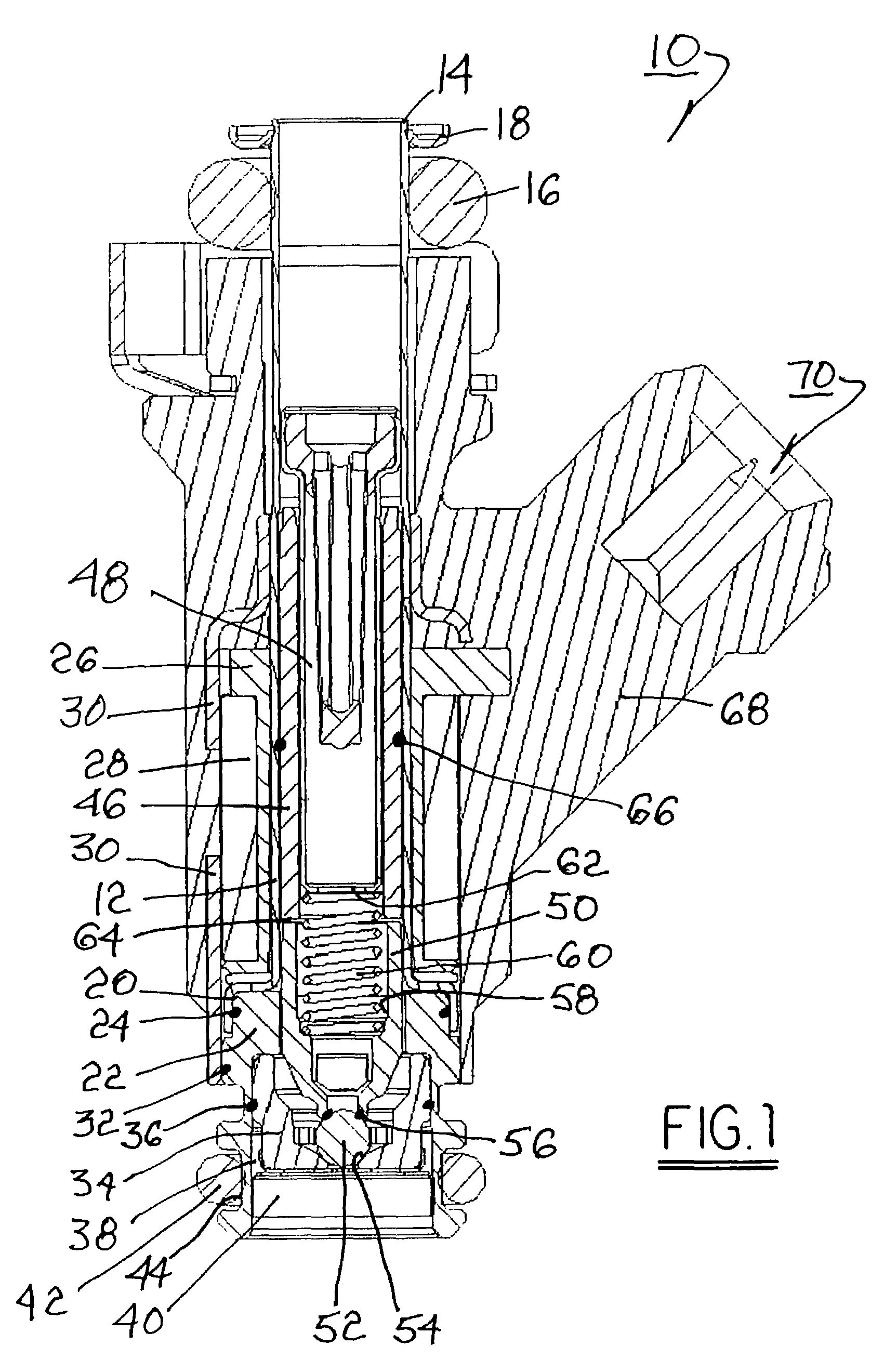
[0017]A solenoid-type fuel injector assembly 10 in accordance with the invention, as depicted in FIG. 1, includes at least one component formed of stabilized ferritic stainless steel, preferably of solenoid quality, comprising a fuel-tube laser welded to an injector body and to a solenoid pole piece. Such solenoids are suited for use in internal combustion engines of automotive vehicles and the like, and can also be used in a variety of other fuel systems such as in marine and aircraft applications.

[0018]The stabilized ferritic stainless steel components used in the solenoid-type fuel injectors of the invention contain chromium (Cr) which may be present in a low amount, from about 10% to about 15%; a medium amount, greater than about 15% but less than about 20%; or a high amount, greater than about 20% but less than about 35%. Preferably, the stabilized ferritic stainless steel comprises about 12% to about 25% chromium, and more preferably, about 12% to about 19% chromium, expressed...


PUM

PropertyMeasurementUnit
Fractionaaaaaaaaaa
Fractionaaaaaaaaaa
Fractionaaaaaaaaaa

Abstract

A solenoid-type fuel injector assembly having at least one component formed of stabilized, solenoid-quality ferritic stainless steel. In a preferred embodiment, an austenitic fuel tube is laser-welded to an injector body and to a solenoid pole piece formed of the subject material. The stabilized, solenoid-quality ferritic stainless steel, preferably a free-machining grade thereof, comprises from about 10% to about 35% chromium, and at least one stabilizing element selected from the group consisting of titanium and columbium. Components thus formed are weldable, exhibit soft magnetic properties sufficiently strong for carrying a magnetic flux in a solenoid pole piece, have desired structural and mechanical properties, and reduce the susceptibility of a solenoid-type fuel injector to metallurgical sensitization and intergranular corrosive attack at weld sites.

Description

TECHNICAL FIELD[0001]The present invention relates to solenoid-type fuel injectors; more particularly, to such fuel injectors having ferritic stainless steel components; and most particularly, to such fuel injectors wherein at least one of the components is formed of a solenoid-quality stabilized ferritic stainless steel.BACKGROUND OF THE INVENTION[0002]Solenoid-type fuel injectors typically are assembled by welding together non-stabilized ferritic stainless steel components, such as a metal tubular injection body welded to a metal fuel tube. Such welding may be carried out by various techniques, including microplasma welding, but typically employs a laser with a continuous laser beam to melt and fuse the components at the bonding surfaces, forming multiple laser weld sites. A slipover injection molded plastic sleeve typically is employed to cover the weld sites; however, this can enhance corrosion at the covered weld sites by fostering an oxygen depletion condition.[0003]The proces...

Claims


Application Information

Patent Timeline
IPC IPC(8): F02M51/00F02M51/06F02M61/16F16K31/06
CPCF02M51/0667F02M61/166F16K31/0651F16K31/0665Y10S239/19
Inventor MOLNAR, JAMES R.
Owner DELPHI TECH IP LTD
Why Eureka
Try Eureka