Methods for producing pattern-forming body

a pattern-forming body and pattern-forming technology, applied in the field of pattern-forming bodies, can solve the problems of difficulty in forming patterns at a high accuracy, adverse effects on some types of pattern-forming bodies, and associated with positioning accuracy, and achieve high quality, high accuracy, and high precision. the effect of microlenses

Inactive Publication Date: 2007-08-07
DAI NIPPON PRINTING CO LTD
View PDF4 Cites 80 Cited by
  • Summary
  • Abstract
  • Description
  • Claims
  • Application Information

AI Technical Summary

Benefits of technology

[0011]Accordingly, a method is desired by which a pattern-forming body can be produced at a high accuracy with no need of the post-exposure treatment without allowing any photocatalyst to remain in the resultant pattern-forming body whereby eliminating any problematic effect of the photocatalyst in the pattern-forming body itself.

Problems solved by technology

While the heat mode recording material is advantageous due to the ability of producing a printing plate only by forming an image simply by a laser beam without processes for example of development, it poses problems associated with adjustment of the laser intensity, disposal of the residues such as a laser-degenerated solid substance, printing resistance and the like.
While a highly minute pattern formation by the photolithography is employed for example in a method for forming a colored pattern of a color filter employed in a liquid crystal display, forming a microlens, producing a minute electric circuit board, and producing a chrome mask employed in exposing a pattern, such a method poses a problem for example of the waste liquid disposal due to the requirement of the post-exposure developing with a liquid developer or etching associated with the use of a photoresist, as well as a problematic degradation of a functional substance, if employed as a photoresist, due to alkaline solution employed for developing.
Although an attempt is made to form a highly minute pattern of a color filter and the like by printing, a pattern formed by the printing is problematic with regard to the position accuracy and the like, resulting in a difficulty in forming a pattern at a high accuracy.
Nevertheless, the conventional method for producing a pattern-forming body using a photocatalyst can not avoid the aspect that the resultant pattern-forming body itself contains the photocatalyst which may affect some types of the pattern-forming body adversely.
However, the exposure via a photomask needs to position the photomask precisely, resulting in a problem associated with the accuracy of the positioning especially when forming a highly minute pattern.
In such a case, a disadvantage may be experienced in forming a highly minute pattern due to the scattering of the light irradiated.

Method used


Image

  • Methods for producing pattern-forming body
  • Methods for producing pattern-forming body
  • Methods for producing pattern-forming body

Examples


embodiment 1

(1) Embodiment 1

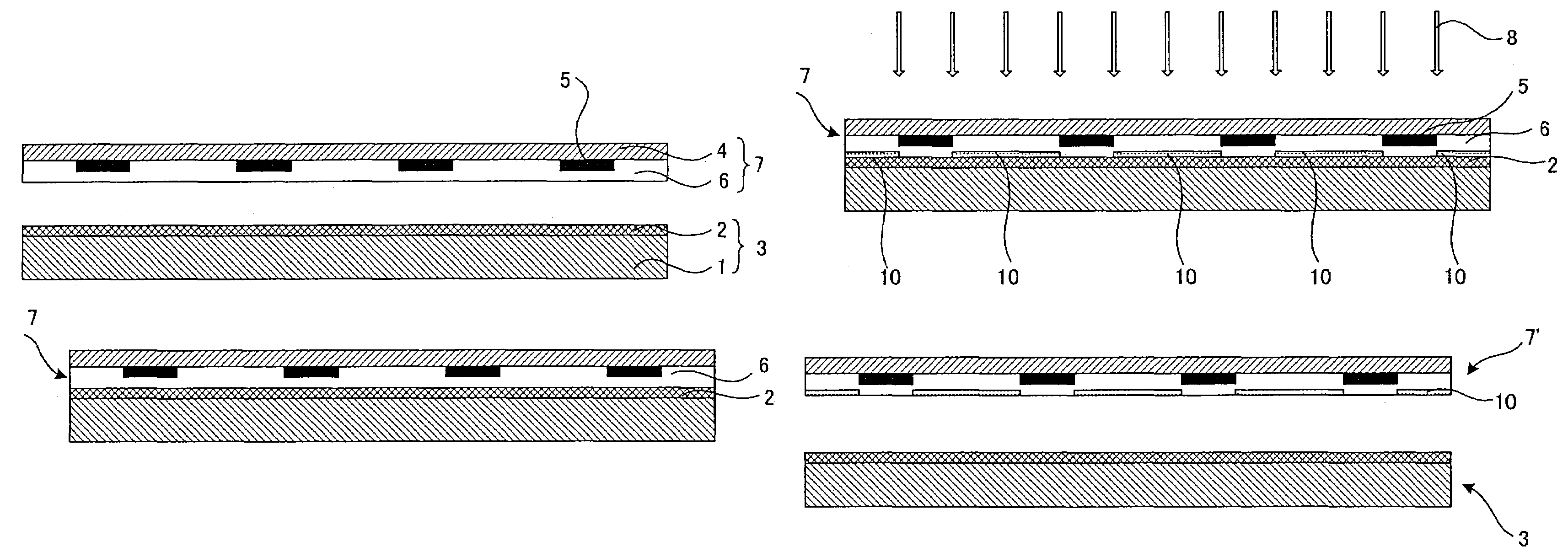
[0095]Embodiment 1 of a pattern-forming body substrate of the present invention relates to a pattern-forming body substrate having a characteristic-changeable layer, a light-shading part, and a transparent substrate. Each component is discussed below.

(Characteristic-changeable Layer)

[0096]A characteristic-changeable layer of this embodiment is discussed first. A characteristic-changeable layer of this embodiment is not limited particularly provided that its characteristics are changed by the effect of a photocatalyst-containing layer described above. For example, the characteristic-changeable layer may be converted to a layer that can be colored by the effect of the photocatalyst by admixing a photochromic material such as spiropyran or an organic dye decomposable by the effect of the photocatalyst with the characteristic-changeable layer.

[0097]It is also possible to use as a characteristic-changeable layer a layer whose adhesiveness to various materials is improved ...

embodiment 2

(2) Embodiment 2

[0194]Embodiment 2 of a pattern-forming body substrate of the present invention is described below. A pattern-forming body substrate in this embodiment has a characteristic-changeable layer having a self supporting property on which a light-shading part is formed as a pattern.

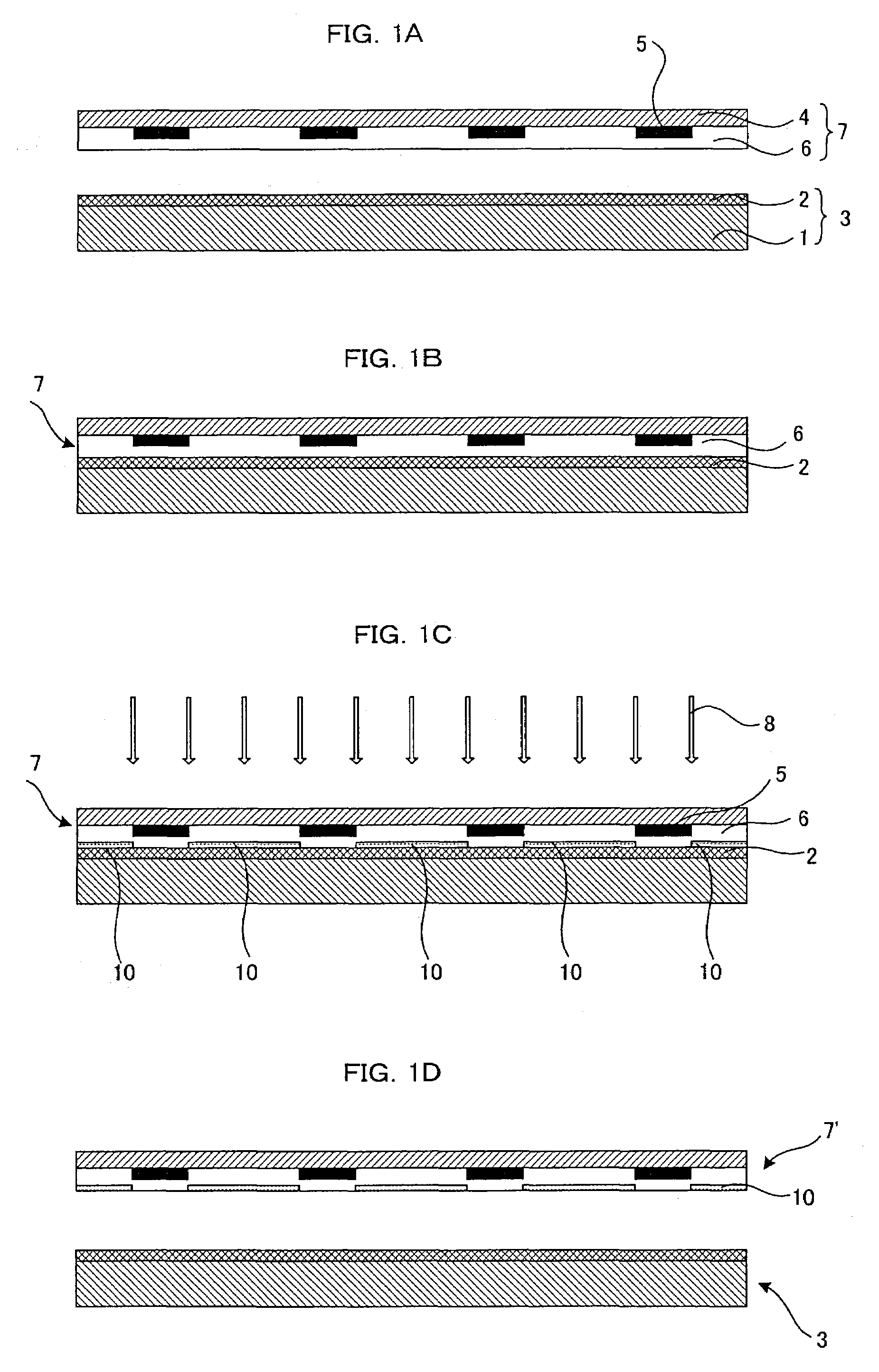
[0195]FIG. 2 shows an example of a pattern-forming body substrate employed in this embodiment, in which a light-shading part 5 is formed on either surface of a characteristic-changeable layer 6 to form a pattern-forming body substrate.

(Characteristic-changeable Layer)

[0196]First, a characteristic-changeable layer in this embodiment is discussed. A characteristic-changeable layer in this embodiment is not limited particularly provided that it is a layer whose characteristics are changed by the effect of a photocatalyst-containing layer and which has a self supporting property, and may be a layer whose color, polarity, or adhesiveness is changed by the effect of a photocatalyst similarly to Embodi...

example 1

[0254]A fluorine-based silicone was formed as a film whose thickness is 0.1 μm on a quartz glass substrate having a pattern of a 0.2 μm-thick and 20 μm-wide chromium line formed an interval of 100 μm to form a wettability-changeable layer to provide a pattern-forming body substrate.

[0255]The fluorine-based silicone employed here was prepared by admixing 5 g of a fluoroalkylsilane (GE Toshiba Silicones, TSL8233) with 3 g of 1N hydrochloric acid, stirring for 24 hours, subjected to 10-fold dilution with isopropyl alcohol to obtain a coating solution, which was then applied by a spin coating method and dried to form a film.

[0256]On a soda lime glass substrate, ST-K01 (Ishihara Sangyo Kaisha, Ltd.) was applied to provide a photocatalyst-containing layer-sided substrate having a photocatalyst-containing layer whose thickness was 0.2 μm. The substrate was arranged in such a manner that the wettabilty change layer was facing the photocatalyst-containing layer at the distance of 5 μm, and i...


PUM

PropertyMeasurementUnit
distanceaaaaaaaaaa
distanceaaaaaaaaaa
contact angleaaaaaaaaaa

Abstract

A method of producing a pattern-forming body with high accuracy with no need for a post-exposure treatment and without allowing any photocatalyst to remain in the resultant pattern-forming body and whereby any problematic effect of the photocatalyst in the pattern-forming body is eliminated. The method includes providing a photocatalyst-containing layer-sided substrate and a pattern-forming body substrate having a characteristic-changeable layer, which is changed by the effect of the photocatalyst in the photocatalyst-containing layer, and a light-shading part formed as a pattern in such a manner that the photocatalyst-containing layer and the characteristic-changeable layer are brought into contact with each other, followed by exposure on the side of the pattern-forming body substrate to change the characteristics of the characteristic-changeable layer of the exposed part, followed by removing the photocatalyst-containing layer-sided substrate.

Description

BACKGROUND OF THE INVENTION[0001]The present invention relates to a method for producing a pattern-forming body comprising a pattern having different characteristics on the surface that can be used in various applications such as a color filter.[0002]Various methods for producing pattern-forming bodies having various patterns such as graphics, images, texts and circuits on substrates have been proposed.[0003]For example, when discussing a case of printing as an example, a planographic plate employed in a planographic printing which is one of the printing methods is employed in such a manner that a plate having a pattern comprising an ink-receiving lipophilic part and a printing ink-repelling part is produced and used to form an image of the ink to be printed on the lipophilic part and the image thus formed is then transferred for example onto a paper whereby accomplishing the printing. In such a printing, a pattern such as a text or figure is formed on such a master printing plate t...

Claims


Application Information

Patent Timeline
Patent Type & Authority Patents(United States)
IPC IPC(8): G03F7/00G03F7/038G03F7/039G03F7/20G02B5/20B05D3/02B32B3/00B32B9/06G02B3/00G03F9/00H05K3/00H05K3/04H05K3/18
CPCB82Y30/00Y10T428/24802Y10T428/24917Y10T428/31663
Inventor KOBAYASHI, HIRONORI
Owner DAI NIPPON PRINTING CO LTD
Why Eureka
Try Eureka