Method and apparatus for spatially limited excitation of an optical transition

a technology of spatial limitation and excitation, applied in the direction of optical radiation measurement, fluorescence/phosphorescence, instruments, etc., can solve the problem of limiting the application of stimulation light to those cases in which the stimulation light has twice the wavelength of the excitation light, and the apparatus for the realization of this method requires extremely high alignment efforts

Inactive Publication Date: 2007-08-07
MAX PLANCK GESELLSCHAFT ZUR FOERDERUNG DER WISSENSCHAFTEN EV
View PDF4 Cites 35 Cited by
  • Summary
  • Abstract
  • Description
  • Claims
  • Application Information

AI Technical Summary

Benefits of technology

[0015]The wave fronts of the partial beams of the de-excitation light beam are preferably aberrated in the same way. This symmetry of the aberrated partial beams ensures that the interference intensity minimum at the focal point is kept at zero level, while the neighboring secondary minima are subject to blur induced by the abberation.
[0016]The wave fronts of the partial beams are aberrated in an identical and simple way in that the wave fronts of the de-excitation light beam are aberrated prior to the division into the partial beams. In this way, the aberrations of the wave fronts of both partial beams are identical so that there is no risk that the intensity minimum in the interference pattern of the partial beams at the focus point is affected.

Problems solved by technology

In this prior art, the limitation to those cases in which the stimulation light has twice the wavelength of the excitation light is a serious drawback.
Besides, an apparatus for the realization of this method requires extremely high alignment efforts since both the excitation light beam and the stimulation light beam have to be split up into partial beams and to be focused out of opposite directions into the same focal area.
While the excitation partial beam pair has to be brought to constructive interference, the stimulating partial beam pair has to be brought to destructive interference at the same geometrical focal point.

Method used


Image

  • Method and apparatus for spatially limited excitation of an optical transition
  • Method and apparatus for spatially limited excitation of an optical transition
  • Method and apparatus for spatially limited excitation of an optical transition

Examples


Embodiment Construction

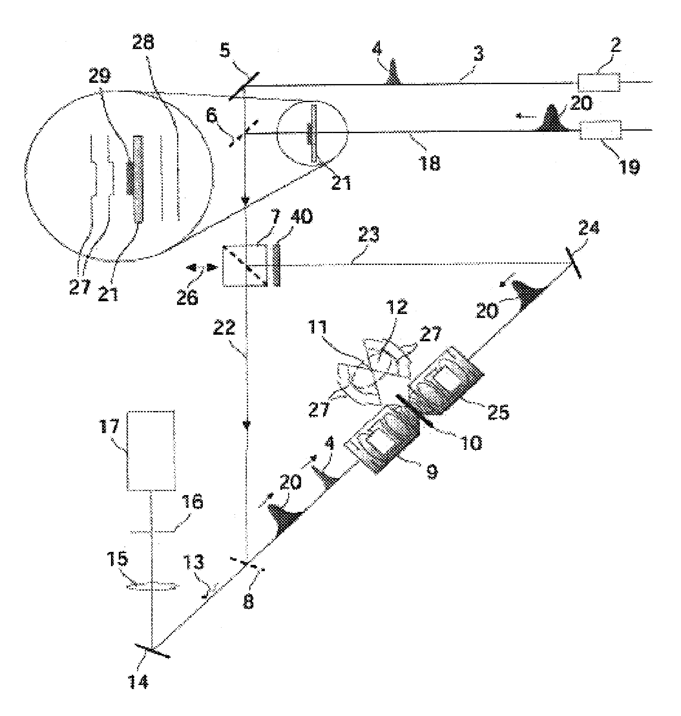
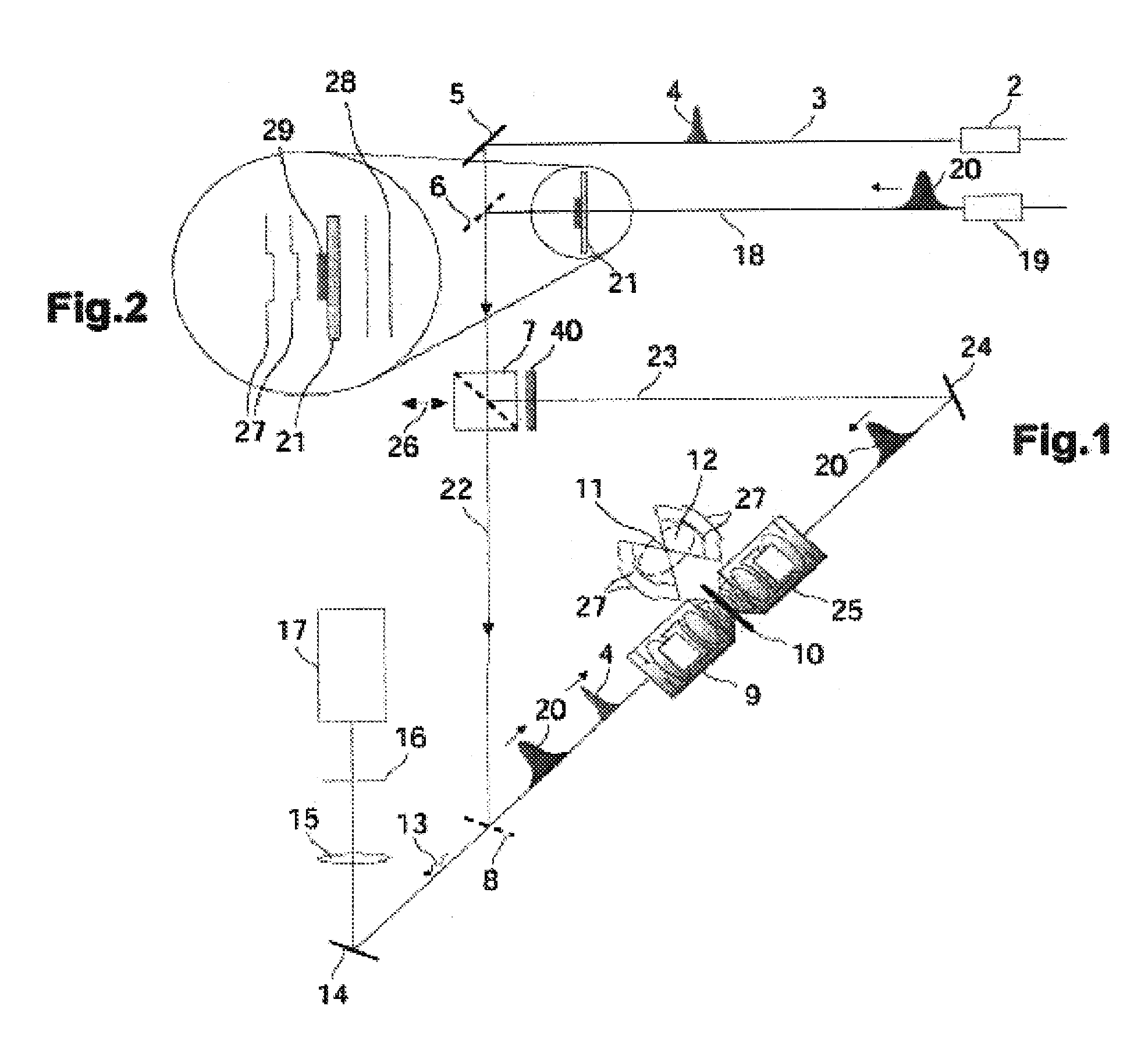
[0046]Referring now in greater detail to the drawings, the apparatus 1 schematically depicted in FIG. 1 comprises an excitation light source 2 providing an excitation light beam 3. The excitation light source 2 provides laser pulses 4 having a wavelength of 554 nm and a pulse duration of 250 fs. The excitation light beam 3 is directed into a first lens system 9 via a mirror 5, through a first dichroic mirror 6 and a beam splitter 7 as well as via a second dichroic mirror 8, and is then focused by the lens system 9 in the area of a sample 10 onto a focal point 11 which is depicted here in an enlarged detail picture besides the sample 10. A partial beam split off from the excitation light beam 3 in the beam splitter 7 is blocked by a wavelength selective element 40 which has no transmission for light having the wavelength of the excitation light beam 3. Because of the diffraction barrier, the excitation light beam 3 is actually not only focused into the zero-dimensional focal point 11...


PUM

PropertyMeasurementUnit
half aperture angleaaaaaaaaaa
angleaaaaaaaaaa
wavelengthaaaaaaaaaa

Abstract

A method of exciting an optical transition in a narrowly limited area of a material comprising the steps of focusing an excitation light beam whose wavelength is tuned to the optical transition to be excited into a focal area extending beyond a focal point; splitting up a de-excitation light beam which is at least somehow influencing the optical transition into at least two partial beams; focusing the at least two partial beams of the de-excitation light beam out of different directions onto the focal point to form a spatially extending interference pattern in the focal area; adjusting a relative phase of the at least two partial beams of the de-excitation light beam so that the interference pattern has an intensity minimum at the focal point and a plurality of intensity maxima on different sides of the focal point; and aberrating the wave fronts of the at least two partial beams of the de-excitation light beam so that the intensity maxima of the interference pattern on different sides of the focal point are spatially expanded without eliminating the intensity minimum at the focal point.

Description

CROSS REFERENCE TO RELATED APPLICATIONS[0001]This application claims priority to co-pending German Patent Application No. 101 54 699.8 entitled “Verfahren und Vorrichtung zum räumlich eng begrenzten Anregen eines optischen Übergangs”, filed Nov. 9, 2001, and is a Continuation in Part of International Patent Application PCT / EP02 / 10456 entitled “Method and Device for physically defined Excitation of an optical Transition”, filed Sep. 18, 2002.FIELD OF THE INVENTION[0002]The invention generally relates to exciting an optical transition in a narrowly limited area of a material. More particularly, the invention relates to a method of exciting an optical transition in a narrowly limited area of a material, comprising the step of superimposing a focal spot of an excitation light beam extending beyond the focal point, the wavelength of the excitation light beam being tuned to the optical transition to be excited, with a spatial interference pattern of a de-excitation light beam that is some...

Claims


Application Information

Patent Timeline
Patent Type & Authority Patents(United States)
IPC IPC(8): G01J3/42G01N21/64G02B21/00
CPCG01N21/6458
Inventor HELL, STEFANDYBA, MARCUS
Owner MAX PLANCK GESELLSCHAFT ZUR FOERDERUNG DER WISSENSCHAFTEN EV
Why Eureka
Try Eureka