
Method and magnetic resonance apparatus for calibrating coil sensitivities

a magnetic resonance and sensitivity technology, applied in the field of method and magnetic resonance mr apparatus, can solve the problems of processing errors, inability to undertake a separate reference scan, and inconvenient operation, and achieve the effects of small flip angle, small fov, and less sensitive to off-resonance effects

Active Publication Date: 2007-08-07
SIEMENS HEALTHCARE GMBH
View PDF1 Cites 19 Cited by
  • Summary
  • Abstract
  • Description
  • Claims
  • Application Information

AI Technical Summary

Benefits of technology

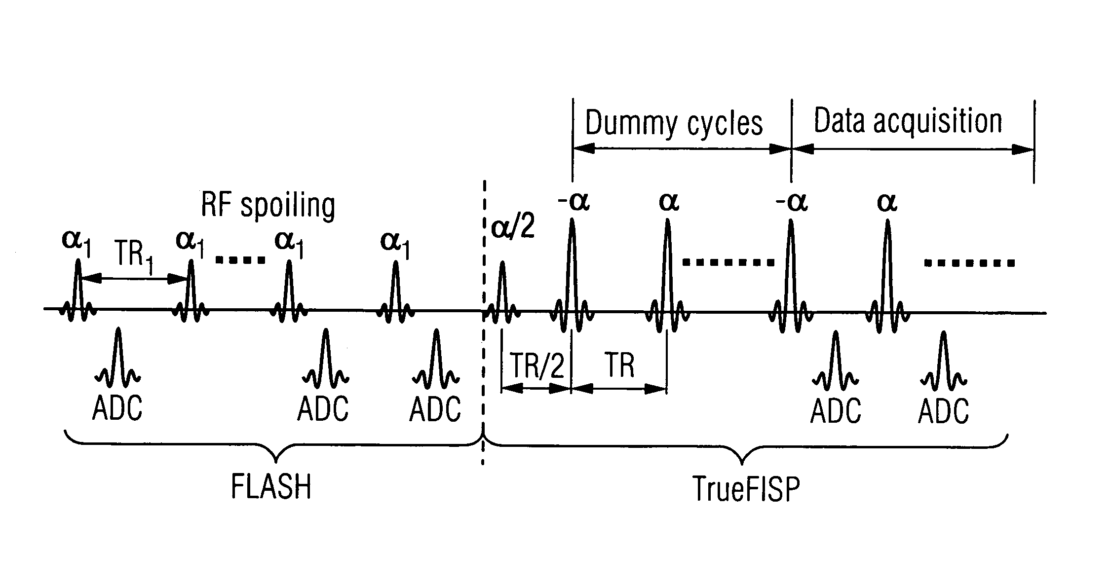
[0014]By using a continuous sequence which is composed of two sequence kernels, the different sequence kernels can be respectively optimized for coil sensitivity calibration and for image acquisition independently of each other so that limitations imposed by the settings for the imaging scans do not affect the reference scans, and vice versa. For example, the reference scans can employ a FLASH kernel, which is less sensitive to off-resonance effects, has a large FOV, a small flip angle, a FatSat pulse, etc. The image acquisition sequence can employ a TrueFISP kernel, which has a smaller FOV, a high flip angle for better signal-to-noise ratio, etc.
[0015]Moreover, the first kernel employed for the coil sensitivity calibration does not have to produce the same contrast as the second kernel used for image acquisition, thereby allowing the calibration scans (reference scans) to be conducted in a very short time hence the ability to use a FLASH kernel with a small flip angle. Because these lines can be acquired rapidly, more reference lines can be obtained to achieve higher resolution and a larger FOV coverage.
[0016]Additionally, moving the reference scans out of the accelerated imaging scans improves the temporal resolution in the imaging scans. Simultaneously, the coil sensitivity calibration can be improved by increasing the number of reference scans without affecting the temporal resolution. A single measurement employing two kernels in succession allows both kernels to share the same slice orientation and position information, which is important in interactive, real-time applications.
[0017]Additionally, the inventive method and apparatus minimize the time delay between the coil sensitivity calibration and the image acquisition, and thus the possibility for coil sensitivity misalignment is minimized.
[0018]The inventive method and apparatus are specially suited for cardiac dynamic studies using a steady-state sequence, by taking advantage of the conventional “dummy” heartbeat for a steady state preparation, and thus no additional data acquisition time is required. Moreover, the image reconstruction can be initiated immediately after all of the calibration scans have been completed, and therefore the image reconstruction time can be reduced compared to the aforementioned self-calibration method.

Problems solved by technology

Processing errors would occur if the signals were processed based on the assumption that all of the coil sensitivities are identical.
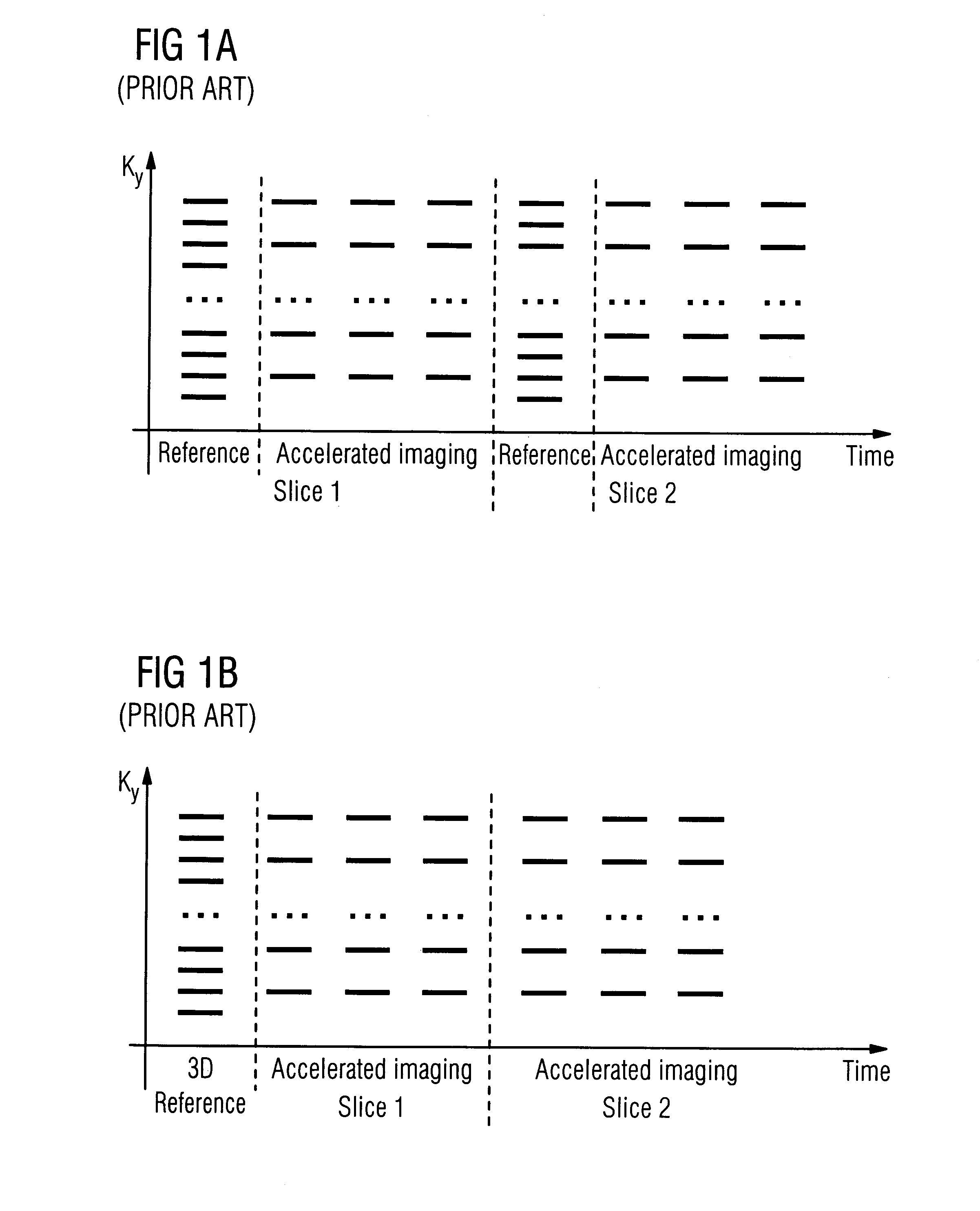
A disadvantage associated with this method (both versions) is that the separation of the reference scan and the imaging scan in different signal acquisition measurements may cause coil sensitivity misalignment between the two types of scans, and thus artifacts may arise in the reconstructed images.
Moreover, in real time magnetic resonance scans, the slice orientation and position may be adjusted interactively, and therefore it is not convenient, and may not be possible, to undertake a separate reference scan each time the slice is redefined.
Data sharing between the reference scan or scans, and the imaging scans, introduces additional engineering workloads.
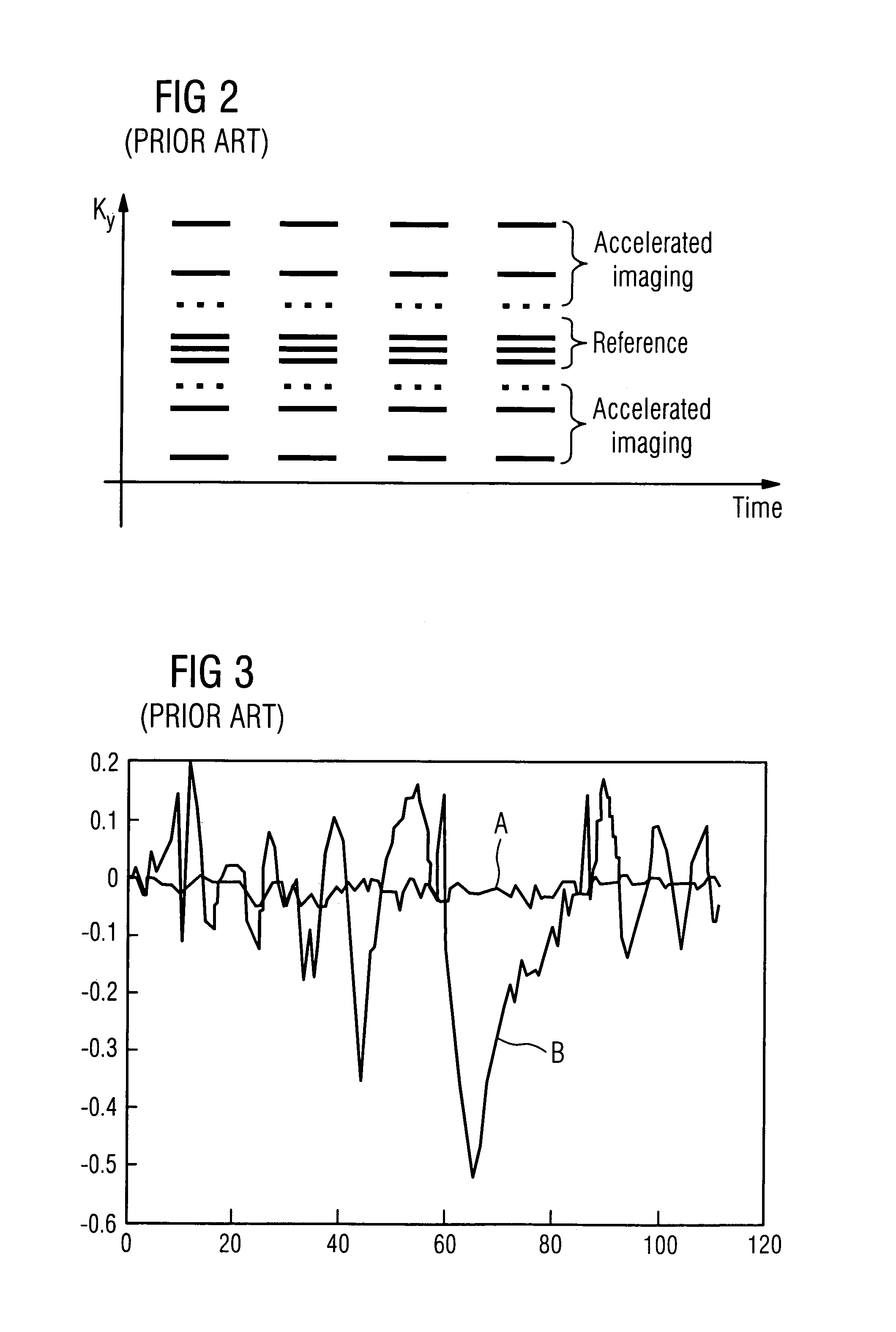
Nevertheless, there are several problems associated with self-calibration.
First, the acquisition of additional k-space centerlines represents a substantial obstacle to improving data acquisition efficiently.
Second, reference scans are limited by the imaging parameters that are defined for the accelerated imaging scans, such as field of view (FOV), bandwidth, etc.

Method used


Image

  • Method and magnetic resonance apparatus for calibrating coil sensitivities
  • Method and magnetic resonance apparatus for calibrating coil sensitivities
  • Method and magnetic resonance apparatus for calibrating coil sensitivities

Examples


Embodiment Construction

[0025]FIG. 4 schematically illustrates a magnetic resonance imaging (tomography) apparatus for generating a nuclear magnetic image of a subject according to the present invention. The components of the nuclear magnetic resonance tomography apparatus correspond to those of a conventional tomography apparatus, but it is controlled according to the invention. A basic field magnet 1 generates a time-constant, intense magnetic field for polarization (alignment) of the nuclear spins in the examination region of a subject such as, for example, a part of a human body to be examined. The high homogeneity of the basic magnetic field required for the nuclear magnetic resonance measurement is defined in a spherical measurement volume M in which the part of the human body to be examined is introduced. For supporting the homogeneity demands and, in particular, for eliminating time-invariable influences, shim plates of ferromagnetic material are attached at suitable locations. Time-variable influe...


PUM


Abstract

In a method and magnetic resonance imaging apparatus wherein magnetic resonance signals are simultaneously received from an examination subject by multiple reception coils, a single, uninterrupted pulse sequence is executed which includes reference scans of the subject with a first sequence kernel that is optimized for coil sensitivity calibration, immediately followed by a series of accelerated image scans with a second sequence kernel, different from the first sequence kernel, that is optimized for imaging. Coil sensitivity maps for the respective coils are calculated from the data acquired in the reference scans, and an image of the subject is reconstructed by operating on the image data with a parallel reconstruction algorithm employing the calculated coil sensitivity maps.

Description

BACKGROUND OF THE INVENTION[0001]1. Field of the Invention[0002]The present invention is directed to a method and magnetic resonance MR apparatus of the type employing multiple coils for obtaining magnetic resonance signals, and in particular to a method and apparatus for calibrating the sensitivities of those coils.[0003]2. Description of the Prior Art[0004]Magnetic resonance signals are received with multiple coils in a magnetic resonance imaging apparatus in many types of magnetic resonance imaging sequences. These types of sequences are generally referred to as partially parallel acquisition (PPA) techniques, and include the known SMASH and SENSE sequences, as well as others. Details that are common to most PPA techniques are described in co-pending application Ser. No. 10 / 117,396, filed Apr. 5, 2002 (“Magnetic Resonance Imaging Method and Apparatus Employing Partially Parallel Acquisition,” Griswold), now U.S. Pat. No. 6,841,998, the teachings of which are incorporated herein b...

Claims


Application Information

Patent Timeline
Patent Type & Authority Patents(United States)
IPC IPC(8): A61B5/055G01R33/561
CPCG01R33/5611
Inventor ZHANG, QIANGWANG, JIAMINSIMONETTI, ORLANDOLAUB, GERHARDKIEFER, BERTHOLD
Owner SIEMENS HEALTHCARE GMBH
Learn More