
Medical examination and treatment system

a medical examination and treatment system technology, applied in the field of medical examination and treatment systems, can solve problems such as potential sources of geometrical inaccuracy, and achieve the effect of reducing equipment costs

Active Publication Date: 2007-08-14
VARIAN MEDICAL SYST PARTICLE THERAPY GMBH & CO KG
View PDF12 Cites 47 Cited by
  • Summary
  • Abstract
  • Description
  • Claims
  • Application Information

AI Technical Summary

Benefits of technology

The present invention is about a device that combines an irradiation device with a radiological diagnosis device. This device can potentially save time and provide precise radiation therapy. The device includes a radiation source that emits particle radiation, an X-ray emitter, and a detector. The X-ray emitter is located opposite the target volume to be irradiated with particles. The detector is located between the target volume and the radiation source. The device can be used for medical examination and treatment. The particle radiation has an inverted dose profile with a sharp maximum and minimal damage to healthy layers of tissue. The device can be used for treating tumors that are poorly accessible or close to organs at risk. The radiation source can emit carbon ions, protons, or other ions. The detector can be moved or stationary during the particle irradiation. The invention allows for monitoring the particle beam profile with minimal expense for equipment.

Problems solved by technology

This movement of the patient, however, is a potential source of geometrical inaccuracies in irradiation therapy.

Method used


Image

  • Medical examination and treatment system
  • Medical examination and treatment system

Examples


Embodiment Construction

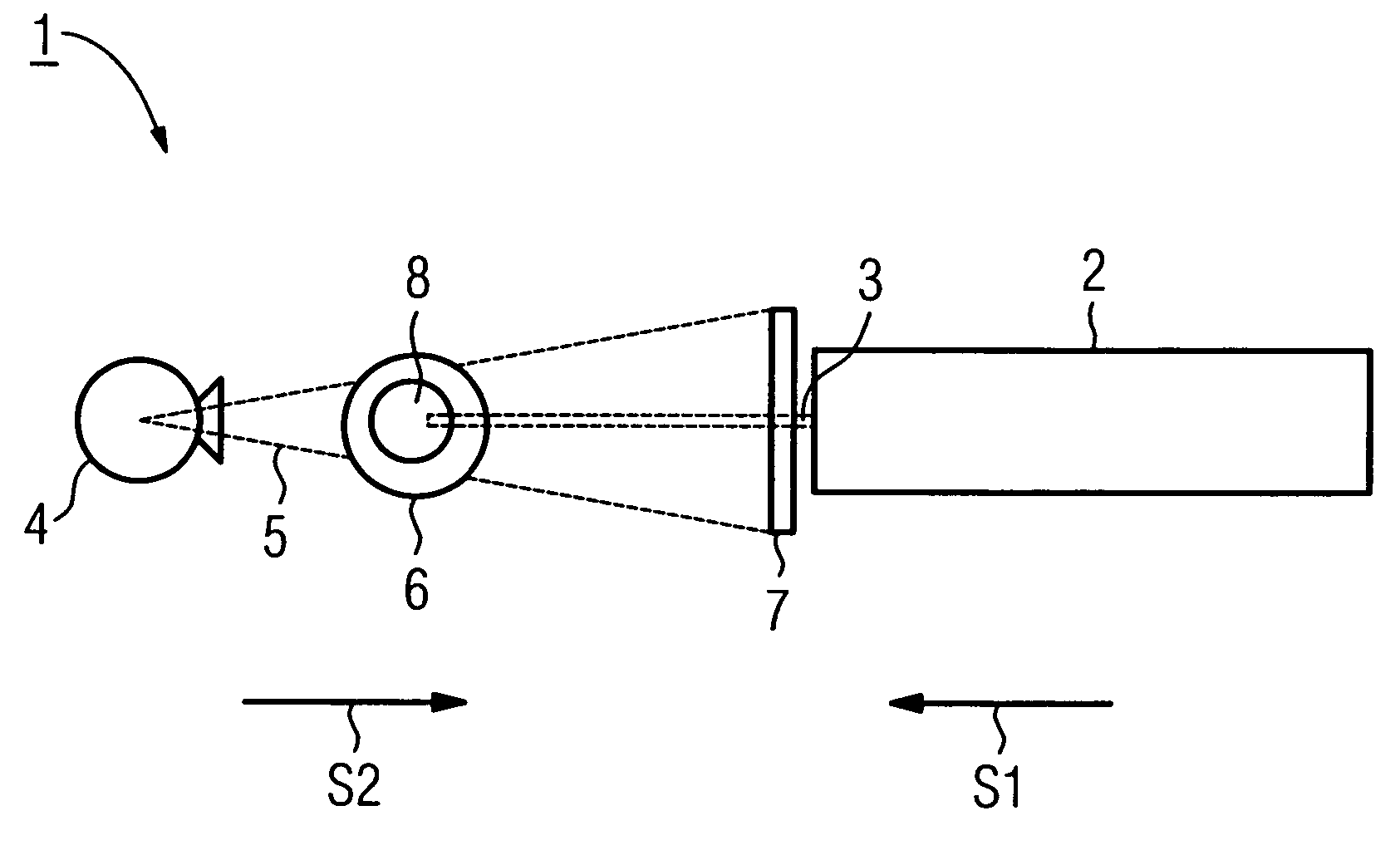
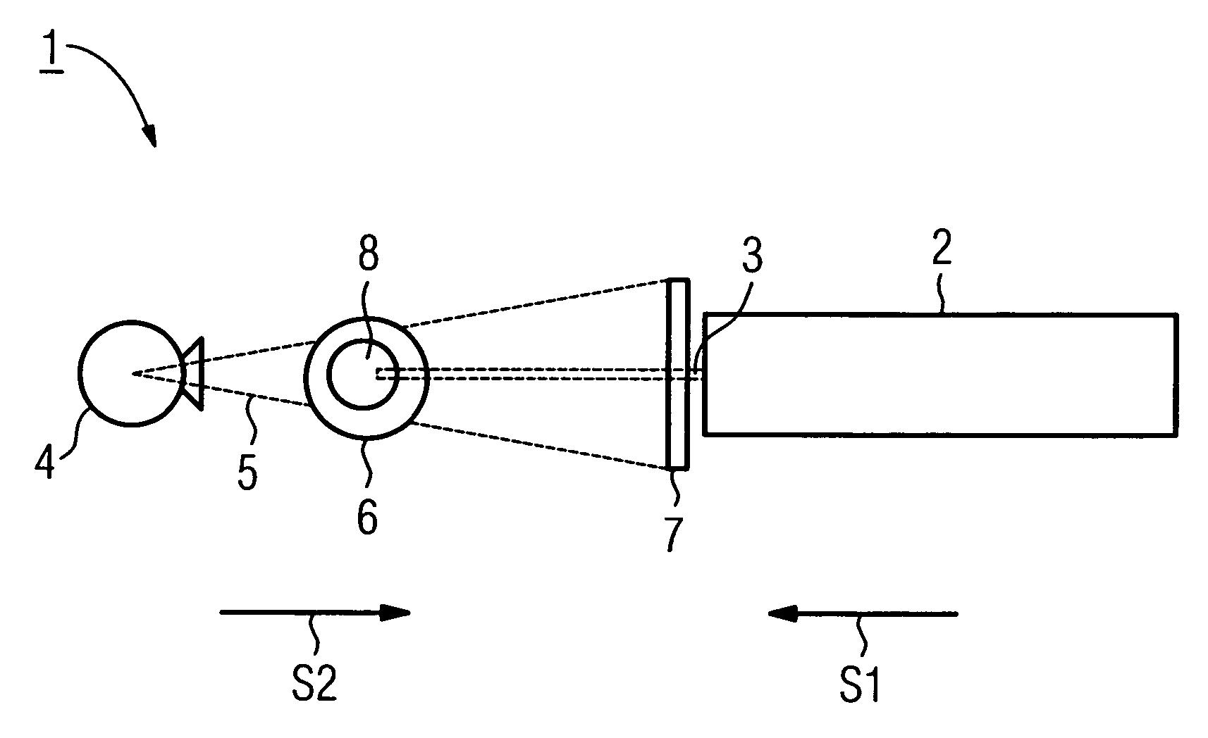
[0014]A medical examination and treatment system 1 includes a radiation source 2, which emits particle radiation 3, for example carbon-ion radiation, and which in a manner not shown in further detail is constructed for example to a synchrotron ring combined with a preceding linear accelerator. The system 1 also includes an X-ray emitter 4, which emits an X-ray beam 5. A radiation direction S1 of the particle radiation 3 is oriented counter or opposite to a radiation direction S2 of the X-ray beam 5. The X-ray beam 5 strikes or penetrates a patient 6, and a projection or image is made on a detector 7, which is located between the patient 6 and the radiation source 2. The detector 7 is operable at least as an X-radiation detector, so that before the therapeutic irradiation, the position of the patient 6 can be detected, and if needed, the patient's position relative to the particle beam 3 can be corrected.

[0015]The particle radiation 3 is aimed substantially exactly at a target volume...


PUM


Abstract

A medical examination and treatment system comprises a radiation source that emits particle radiation, an X-ray emitter located on one side of a target volume and diametrically opposite to the radiation source, and a detector located between the target volume and the radiation source. The target volume is positioned to be exposed to the particle radiation. A radiation direction of the X-ray emitter is oriented opposite to a radiation direction of the particle radiation.

Description

FIELD[0001]The present embodiments relate, in general, to medical systems, and in particular, to a medical examination and treatment system that uses particle radiation, such as heavy-ion radiation.BACKGROUND[0002]An irradiation device for heavy-ion therapy is known for example from German Patent Application DE 198 35 209 A1.[0003]In radiation therapy, an exact aiming of a radiation beam at a target tissue to be treated is of great significance and importance. As such, radiation therapy devices are generally combined with diagnostic devices. For example, a medical irradiation system known from German Patent Application DE 35 02 776 A1 includes a simulator with an X-ray tube and an image amplifier for substantially precise positioning of a patient to be examined. In this German Patent Application, a stationary linear accelerator that emits corpuscular rays is for example provided as the radiation source. An additional X-ray emitter, which is provided for diagnostic applications, can ...

Claims


Application Information

Patent Timeline
Patent Type & Authority Patents(United States)
IPC IPC(8): A61N5/10G21G4/08
CPCA61N5/1049A61N5/1078A61N2005/1061A61N2005/1087
Inventor SOMMER, ANDRES
Owner VARIAN MEDICAL SYST PARTICLE THERAPY GMBH & CO KG
Learn More