Hydrogen generator and fuel cell system having the same

a hydrogen generator and fuel cell technology, applied in the direction of combustible gas production, separation processes, instruments, etc., can solve the problems of large amount of reformed gas supplied from the hydrogen generator to the fuel cell, undeveloped infrastructure for hydrogen supply means, and inability to meet the needs of hydrogen generation, etc., to achieve high quality reformed gas, reduce carbon monoxide sufficiently, and achieve the effect of efficient hydrogen production

Active Publication Date: 2007-08-21
PANASONIC CORP
View PDF12 Cites 4 Cited by
  • Summary
  • Abstract
  • Description
  • Claims
  • Application Information

AI Technical Summary

Benefits of technology

[0018]The present invention has been accomplished in view of the above problems, and an object thereof is to provide a hydrogen generator capable of generating a high quality reformed gas which is sufficie

Problems solved by technology

However, hydrogen-supplying means has not been developed as infrastructure.
Such poisoning is an unignorable problem particularly when the solid polymer fuel cell is used as the fuel cell.
More specifically, in the case where the amount of the feed material supplied to the reformer is large, the amount of the reformed gas supplied from the hydrogen generator to the fuel cell is large.
In the case where the temperature of the shift catalyst in the shifter is lowered, it is sometimes impossible to sufficiently reduce carbon monoxide contained in the reformed gas.
This is because the lowered temperature of the shift catalyst causes the water gas shift reaction in the shifter to progress with insufficient yield.
In this case, it is impossible to sufficiently reduce the carbon monoxide concentration in the reformed gas in the succeeding process in the purifier, so that the reformed gas to be supplied to the fuel cell is deteriorated in quality.
However, with the first conventiona

Method used


Image

  • Hydrogen generator and fuel cell system having the same
  • Hydrogen generator and fuel cell system having the same
  • Hydrogen generator and fuel cell system having the same

Examples


first embodiment

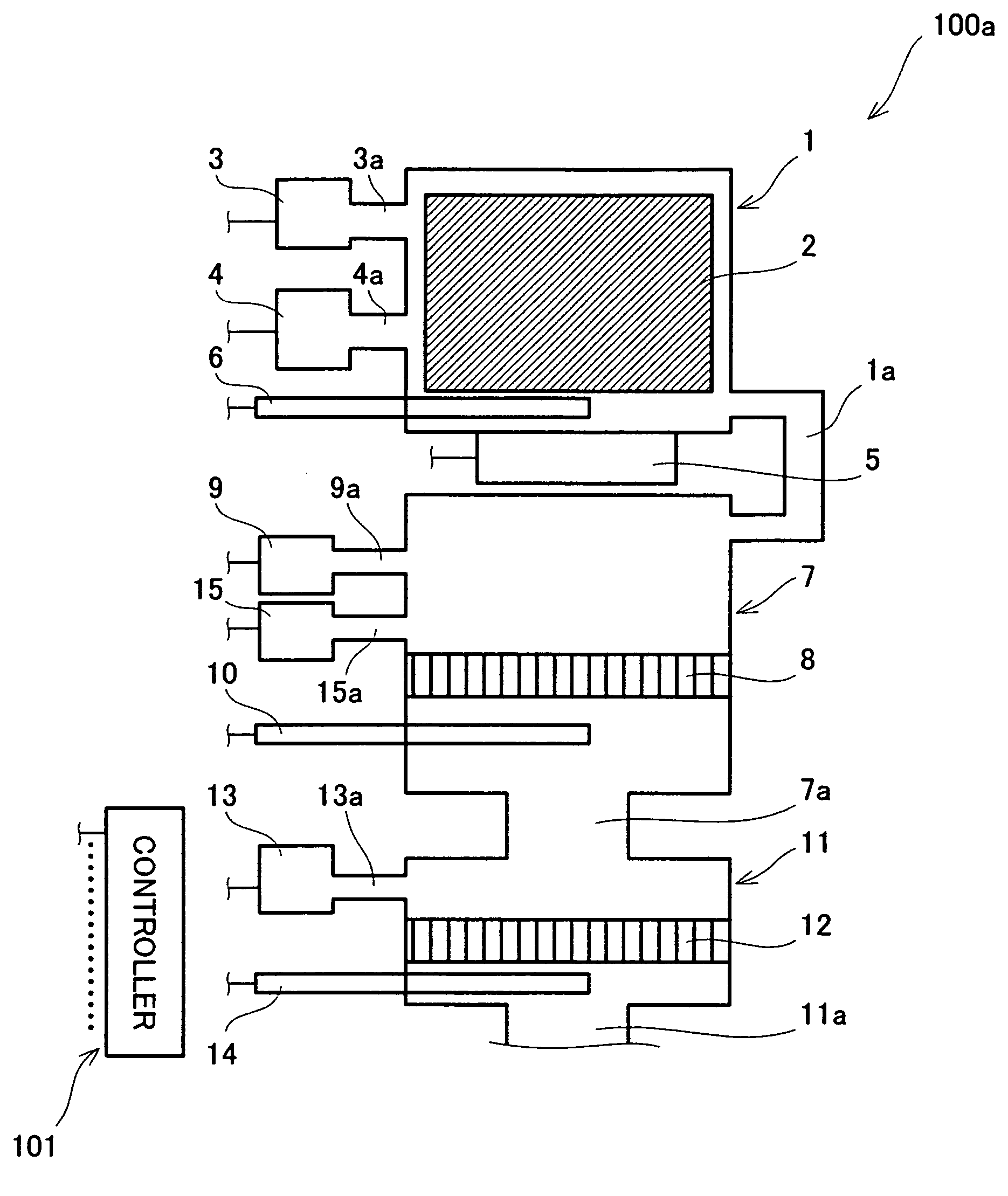
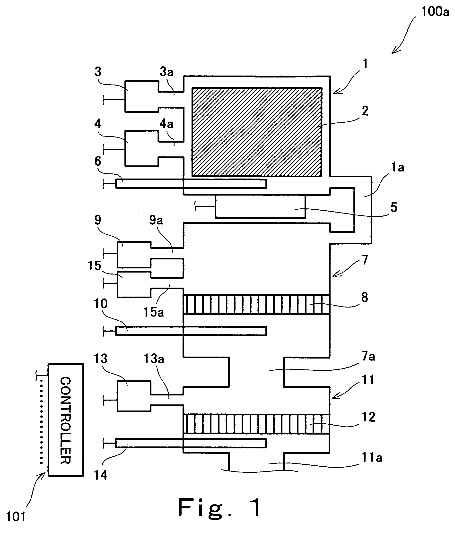
[0036]FIG. 1 is a schematic diagram showing a constitution of a hydrogen generator according to a first embodiment of the invention. Note that the constitution of the hydrogen generator shown in FIG. 1 is extracted from a fuel cell system described later in this specification.

[0037]As shown in FIG. 1, a hydrogen generator 100a according to this embodiment has: a reformer 1 for generating hydrogen by way of a steam reforming reaction of a hydrocarbon-based material such as a natural gas, a liquid propane gas (LPG), naphtha, gasoline, and kerosene or a material containing at least carbon and hydrogen, which is represented by an alcohol-based material and the like such as methanol and the like, with water; a shifter 7 for shifting carbon monoxide which is discharged from the reformer 1 together with hydrogen into hydrogen by way of a water gas shift reaction of carbon monoxide with water; a purifier 11 for converting carbon monoxide which is discharged from the shifter 7 together with ...

second embodiment

[0071]In a hydrogen generator according to the second embodiment, a control program which is stored in a controller 101 to be used for increasing power generation amount is different from that of the hydrogen generator of the first embodiment, and a constitution of hardware of the hydrogen generator is the same as that of the hydrogen generator of the first embodiment. Basic operations of the hydrogen generator performed for generating hydrogen are the same as those of the hydrogen generator of the first embodiment. Therefore, in this embodiment, the constitution of the hardware and the basic operations for generating hydrogen of the hydrogen generator of this embodiment are omitted.

[0072]In this embodiment, in the case of increasing an amount of hydrogen to be generated by the hydrogen generator 100a in accordance with an increase in power generation amount of a fuel cell, the controller 101 judges whether or not a temperature detected by a temperature detector 10 has reached a ref...

third embodiment

[0075]In a hydrogen generator according to the third embodiment, a control program which is stored in a controller 101 to be used for increasing power generation amount is different from that of the hydrogen generator of the first embodiment, and a constitution of hardware of the hydrogen generator is the same as that of the hydrogen generator of the first embodiment. Basic operations of the hydrogen generator performed for generating hydrogen are the same as those of the hydrogen generator of the first embodiment. Therefore, in this embodiment, too, the constitution of the hardware and the basic operations for generating hydrogen of the hydrogen generator of this embodiment are omitted.

[0076]In this embodiment, in the case of increasing an amount of hydrogen to be generated by the hydrogen generator 100a in accordance with an increase in power generation amount of a fuel cell, the controller 101 judges whether or not a temperature detected by a temperature detector 10 has reached a...


PUM


Abstract

A hydrogen generator of the present invention is provided with: a reformer for generating a reformed gas containing hydrogen from a feed material containing an organic compound at least containing carbon and hydrogen and water; a heater for heating the reformer to a temperature required for generating the reformed gas; a carbon monoxide reducing unit having a carbon monoxide reducing catalyst for reducing carbon monoxide contained in the reformed gas generated in the reformer; and a temperature detector for detecting at least one of a temperature of the reformed gas in the carbon monoxide reducing unit and a temperature of the carbon monoxide reducing catalyst, wherein an amount of the feed material to be supplied to the reformer is controlled based on a comparison between a detected temperature detected by the temperature detector and a reference temperature set in accordance with the amount of the feed material.

Description

BACKGROUND OF THE INVENTION[0001]1. Field of the Invention[0002]The present invention relates to a hydrogen generator for generating hydrogen using an organic compound such as methane, town gas, propane, gasoline, and alcohol, and a fuel cell system for generating power by using hydrogen as a fuel.[0003]2. Description of the Related Art[0004]A fuel cell cogeneration system (hereinafter referred to as fuel cell system), which is excellent in power generation efficiency and overall efficiency, has heretofore been noted as a distributed power generating system capable of effectively using energy.[0005]Various types of fuel cells are usable in the fuel cell system. For example, a phosphoric acid fuel cell has been practically used as the fuel cell. A solid polymer fuel cell, for example, is under development for its practical use.[0006]Well, many of the fuel cells currently used in the fuel cell system generate power by using hydrogen as a fuel. However, hydrogen-supplying means has not...

Claims


Application Information

Patent Timeline
IPC IPC(8): B01D1/00B01J8/04B01J19/00C01B3/38C01B3/48C01B3/58H01M8/04H01M8/06
CPCB01J8/048B01J19/0013C01B3/38C01B3/48C01B3/583H01M8/04007H01M8/0612H01M8/0662B01J8/0488Y02E60/50B01J2219/00063B01J2219/002B01J2219/00209B01J2219/00213B01J2219/00227C01B2203/00C01B2203/0233C01B2203/0283C01B2203/044C01B2203/047C01B2203/066C01B2203/0811C01B2203/1023C01B2203/1041C01B2203/1052C01B2203/1064C01B2203/107C01B2203/1082C01B2203/1217C01B2203/1235C01B2203/1619C01B2203/1623C01B2203/1685C01B2203/169C01B2203/1695C01B2203/82
Inventor FUJIHARA, SEIJIUKAI, KUNIHIROTAGUCHI, KIYOSHIWAKITA, HIDENOBU
Owner PANASONIC CORP
Why Eureka
Try Eureka