Superelastic guiding member

a superelastic and guiding member technology, applied in the field of medical devices, can solve the problems of specimen occurrence, 52% of alloy becoming too brittle to fabricate by cold working, etc., and achieve the effects of uniform residual stress in the material, one-to-one torque response, and adequate ductility

Inactive Publication Date: 2007-08-21
ABBOTT CARDIOVASCULAR
View PDF69 Cites 20 Cited by
  • Summary
  • Abstract
  • Description
  • Claims
  • Application Information

AI Technical Summary

Benefits of technology

[0022]The elongated body of the invention exhibits a stress-induced austenite-to-martensite phase transformation over a broad region of strain at very high, relatively constant stress levels. As a result a guiding member formed of this material is very flexible, it can be advanced through very tortuous passageways such as a patient's coronary vasculature with little risk that the superelastic portion of the guiding member will develop a permanent set and at the same time it will effectively transmit the torque applied thereto without causing the guiding member to whip.

Problems solved by technology

The stress-strain relationship determined by applying a bending moment to a cantilevered specimen is slightly different from the relationship determined by tensile testing because the stresses which occur in the specimen during bending are not as uniform as they are in tensile testing.
At nickel levels above,52% the alloy becomes too brittle to fabricate by cold working.

Method used


Image

  • Superelastic guiding member
  • Superelastic guiding member
  • Superelastic guiding member

Examples


Embodiment Construction

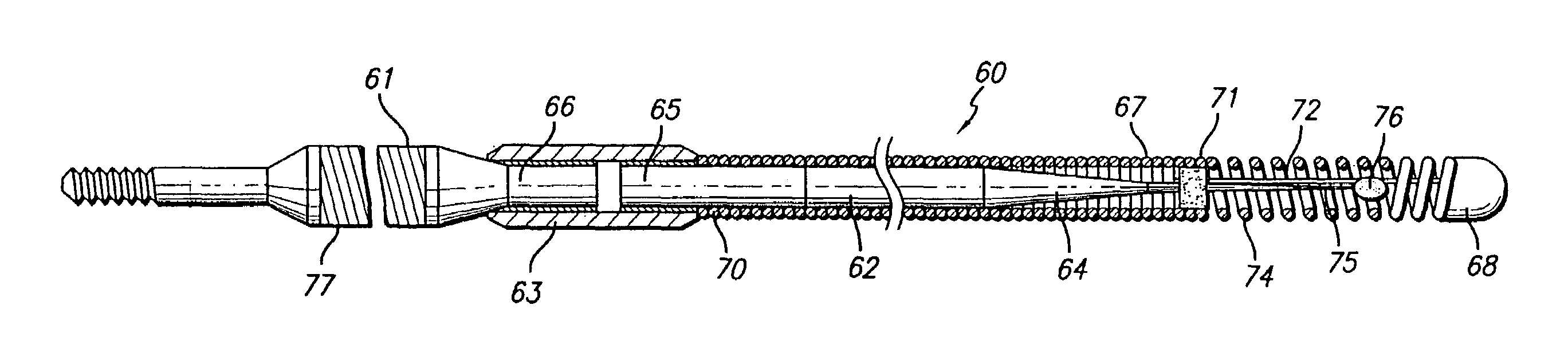
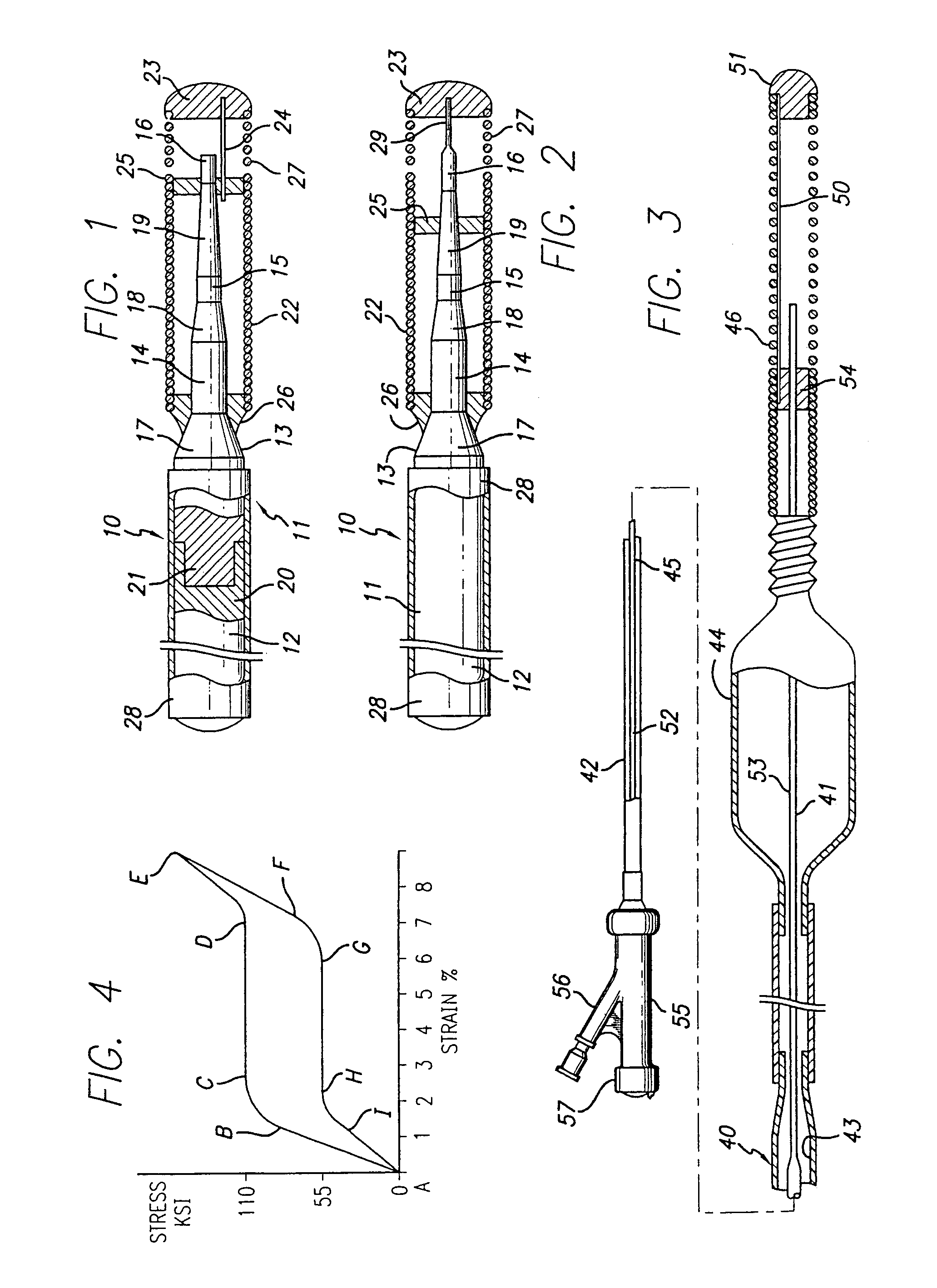
[0030]FIG. 1 illustrates a guidewire 10 embodying features of the invention that is adapted to be inserted into a body lumen such as an artery. The guidewire 10 comprises an elongated body or core member 11 having an elongated proximal portion 12 and a distal portion 13, at least part of which, preferably the distal portion, is formed of superelastic material of the invention. The distal portion 13 has a plurality of sections 14, 15 and 16 having sequentially smaller diameters, with tapered sections 17, 18 and 19 connecting the smaller diameter sections with adjacent sections. The elongated proximal portion 12 is provided with a female distal end 20 which receives the male end 21 of the distal portion 13. The ends 20 and 21 may be press fit together or may be secured together by means such as a suitable adhesive or by welding, brazing or soldering.

[0031]A helical coil 22 is disposed about the distal portion 13 and has a rounded plug 23 on the distal end thereof where the distal end ...


PUM

PropertyMeasurementUnit
wall thicknessaaaaaaaaaa
outer diameteraaaaaaaaaa

Abstract

An improved guiding member for use within a body lumen having a unique combination of superelastic characteristics. The superelastic alloy material has a composition consisting of about 30% to about 52% (atomic) titanium, and about 38% to 52% nickel and may have one or more elements selected from the group consisting of iron, cobalt, platinum, palladium, vanadium, copper, zirconium, hafnium and niobium. The alloy material is subjected to thermomechanical processing which includes a final cold working of about 10 to about 75% and then a heat treatment at a temperature between about 450° and about 600° C. and preferably about 475° to about 550° C. Before the heat treatment the cold worked alloy material is preferably subjected to mechanical straightening. The alloy material is preferably subjected to stresses equal to about 5 to about 50% of the room temperature ultimate yield stress of the material during the thermal treatment. The guiding member using such improved material exhibits a stress-induced austenite-to-martensite phase transformation at an exceptionally high constant yield strength of over 90 ksi for solid members and over 70 ksi for tubular members with a broad recoverable strain of at least about 4% during the phase transformation. An essentially whip free product is obtained.

Description

CROSS-REFERENCE TO RELATED APPLICATIONS[0001]This is a continuation of a co-pending application having U.S. Ser. No. 10 / 291,930, filed Nov. 11, 2002, which is a continuation of application U.S. Ser. No. 10 / 117,155 filed Apr. 5, 2002, now U.S. Pat. No. 6,682,608, which is a continuation of Ser. No. 09 / 589,592 filed Jun. 7, 2000, now U.S. Pat. No. 6,638,372, which is a continuation of Ser. No. 08 / 484,218 filed Jun. 7, 1995, now U.S. Pat. No. 6,165,292, which is a continuation of Ser. No. 08 / 212,431 filed Mar. 11, 1994, abandoned, which is a continuation-in-part of Ser. No. 07 / 994,679 filed Dec. 22, 1992, now U.S. Pat. No. 5,341,818, and is also a continuation-in-part of Ser. No. 07 / 629,381 filed Dec. 18, 1990, now abandoned, the contents of all of which are hereby incorporated by reference.BACKGROUND OF THE INVENTION[0002]This invention relates to the field of medical devices, and more particularly to guiding means such as guidewires for advancing catheters within body lumens in proce...

Claims


Application Information

Patent Timeline
Patent Type & Authority Patents(United States)
IPC IPC(8): A61F2/86A61L31/02C22C14/00C22C30/00C22F1/00
CPCA61L31/022A61L31/14A61M25/09C22C14/00C22C30/00C22F1/006A61L2400/16A61M2025/09008A61M2025/09083A61M2025/09141A61M2025/09175A61M2205/0266
Inventor ABRAMS, ROBERT M.FARIABI, SEPEHR
Owner ABBOTT CARDIOVASCULAR
Why Eureka
Try Eureka