
System, method and apparatus for direct imaging in ultrasonic holography

a technology of ultrasonic holography and system, applied in the field of acoustic imaging, can solve the problems of limiting the practical application of holography to the light domain, e.g., the amount of information displayed for the user in this situation may be too large, and there is no equivalent “film” material to record, so as to achieve the effect of small system footprint and reduced production cos

Inactive Publication Date: 2007-08-21
HOLOGRAPHIC ENG
View PDF6 Cites 8 Cited by
  • Summary
  • Abstract
  • Description
  • Claims
  • Application Information

AI Technical Summary

Benefits of technology

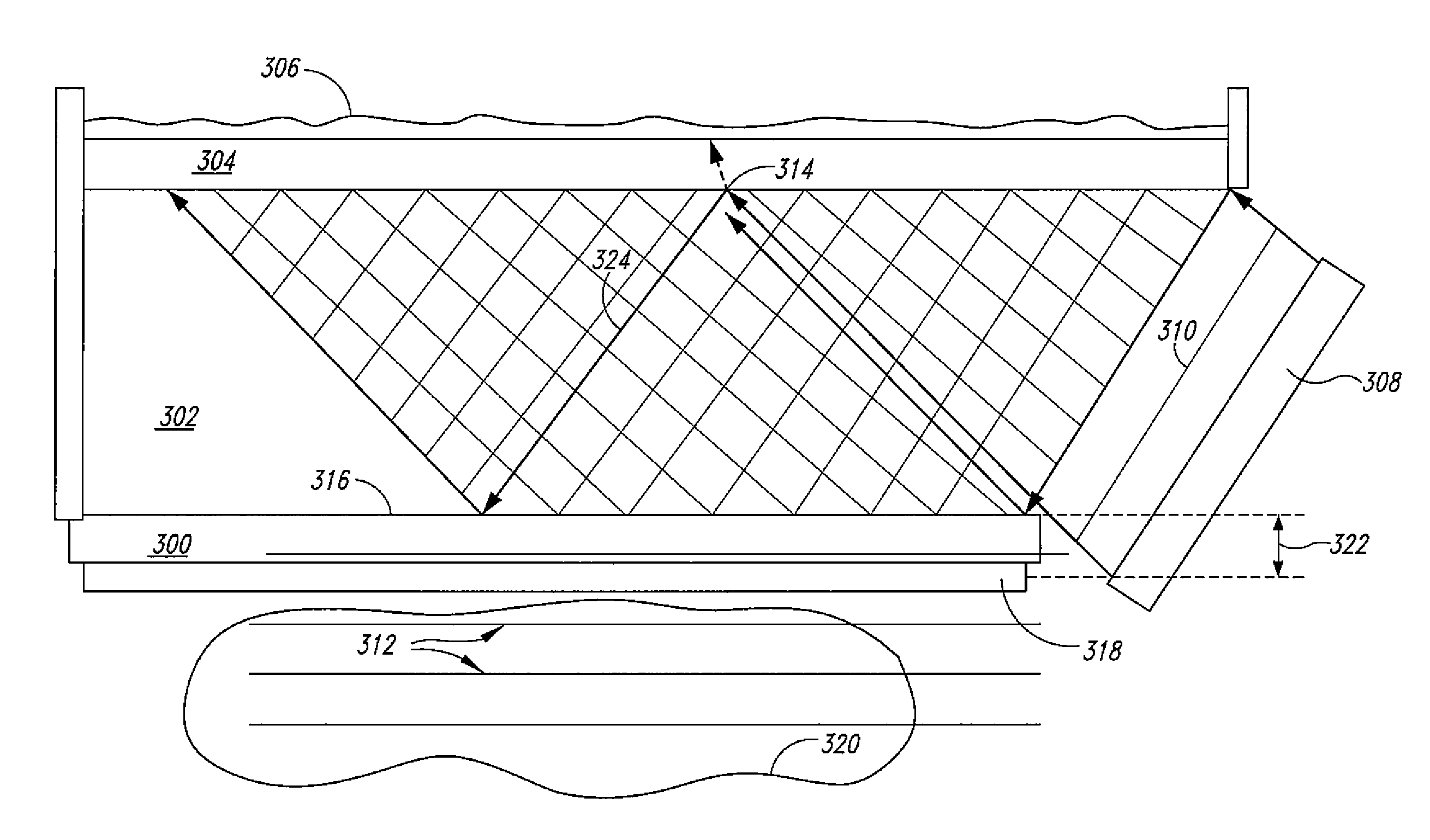
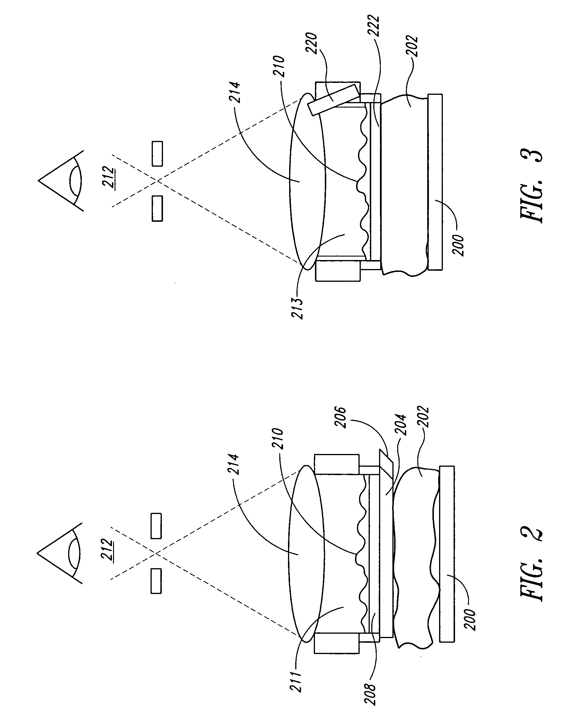
"The present invention provides a process and apparatus for volumetric holographic acoustical imaging that allows for a smaller system footprint, lower cost of production, and greater depth of field compared to prior art. The invention introduces the reference wave in a way that does not interfere with an object placed adjacent to or in close proximity to the hologram surface. The process and apparatus also utilize multiple reference sources and create an off axis acoustic reference wave using a narrow, thin, or liquid-to-liquid interface. The invention allows for the object to be placed adjacent to the holographic detector, increasing the depth of field and reducing the amount of energy required from the object source. The process and apparatus also utilize a narrow fluid filled channel or a liquid-to-gas interface as the acoustic waveguide for the reference wave."

Problems solved by technology

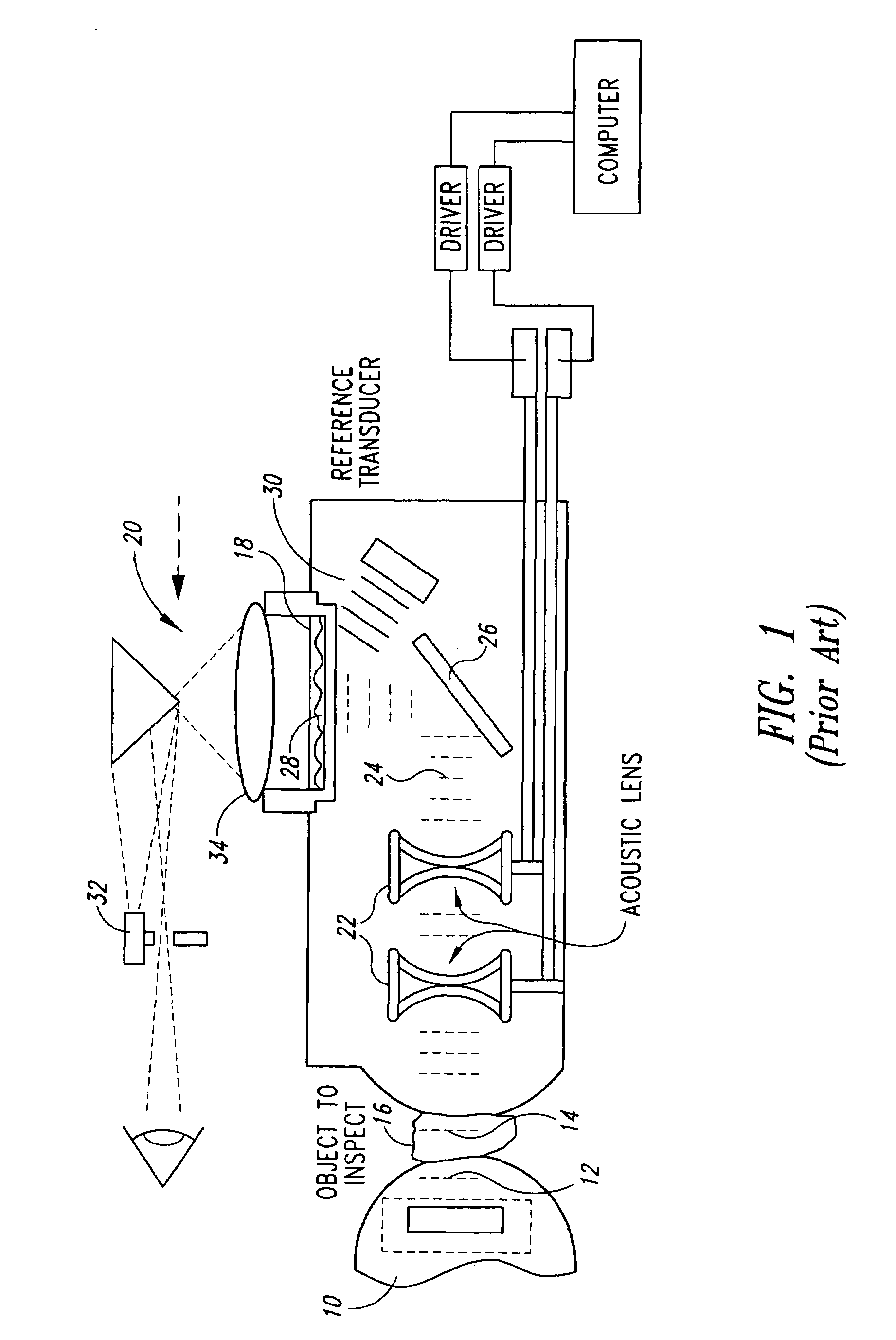
This requirement currently limits practical applications of the practice of holography to the light domain (e.g., a laser light) or the domain of acoustics (sometimes referred to as ultrasound due to the practical application at ultrasonic frequencies) as these two sources are currently the only available coherent energy sources.
However, the amount of information displayed for the user in this situation may be too great.
However, there is no equivalent “film” material to record the intricate phase and amplitude pattern of a complex ultrasonic wave.
The sound energy at the frequency of ultrasound (above range of human hearing) will propagate with little attenuation through a liquid (such as water) but cannot sustain substantial propagation through air.
The density of air (approximately 0.00116 g / cm3) is not sufficient to couple these short wavelengths and allow them to propagate for any significant distance.
Thus, an opportunity to have a full 3-D (three dimensional) view is compromised since the aperture size to the object distance limits the 3-D information.

Method used


Image

  • System, method and apparatus for direct imaging in ultrasonic holography
  • System, method and apparatus for direct imaging in ultrasonic holography
  • System, method and apparatus for direct imaging in ultrasonic holography

Examples


Embodiment Construction

[0035]In the following description, certain specific details are set forth in order to provide a thorough understanding of various embodiments of the invention. However, one skilled in the relevant art will recognize that the invention may be practiced without one or more of these specific details, or with other methods, components, materials, etc. In other instances, well-known structures associated with ultrasonic holography have not been shown or described in detail to avoid unnecessarily obscuring descriptions of the embodiments of the invention.

[0036]Unless the context requires otherwise, throughout the specification and claims which follow, the word “comprise” and variations thereof, such as, “comprises” and “comprising” are to be construed in an open, inclusive sense, that is as “including, but not limited to.”

[0037]Reference throughout this specification to “one embodiment” or “an embodiment” means that a particular feature, structure or characteristic described in connectio...


PUM


Abstract

An acoustical holographic imaging method and apparatus for introducing a reference wave into a hologram surface such that the reference wave does not interfere with an object placed adjacent to or in close proximity to the hologram surface. More particularly, the ultrasonic holographic imaging system may use a reference wave introduced on the side of a thin (3 element) detector that acts as a wave guide; to introduce the reference wave to a liquid-to-gas interface or alternatively, from the topside of the detecting surface through a liquid-to-liquid interface. The system eliminates the acoustic lens system, thereby reducing the size and cost of the system. Further, an object may be placed at the detecting surface, increasing the depth of field of the resultant image and reducing the energy needed from the object source. The system may additionally utilize multiple reference sources.

Description

BACKGROUND OF THE INVENTION[0001]1. Field of the Invention[0002]The present invention is directed generally to acoustic imaging and more particularly the direct imaging of an object utilizing the method of acoustical holography whereby the object being imaged can be in close proximity to the hologram surface.[0003]2. Description of the Related Art[0004]Holography involves combining or interfering an object wave or energy with a reference wave or energy to form an interference pattern referred to as the hologram. A fundamental requirement for the forming of the hologram and the practice of holography is that the initial sources of the object wave and reference wave or energy are coherent with respect to the other wave. That is to say that all parts of both the object wave and the reference wave are of the same frequency and of a defined orientation, namely, a fixed spatial position and angle between the direction of propagation of the two sources. When performing holography the objec...

Claims


Application Information

Patent Timeline
Patent Type & Authority Patents(United States)
IPC IPC(8): G03H1/00
CPCG01N29/0663G01N29/2462G01N29/30G03H3/00G01N2291/0421G01N2291/0422G01N2291/044Y10S359/901
Inventor GARLICK, GEORGE F.GARLICK, TODD F.
Owner HOLOGRAPHIC ENG
Learn More