
Optical wave guide element, and manufacture therefor

Inactive Publication Date: 2007-08-21
SUMITOMO OSAKA CEMENT CO LTD
View PDF19 Cites 0 Cited by
  • Summary
  • Abstract
  • Description
  • Claims
  • Application Information

AI Technical Summary

Benefits of technology

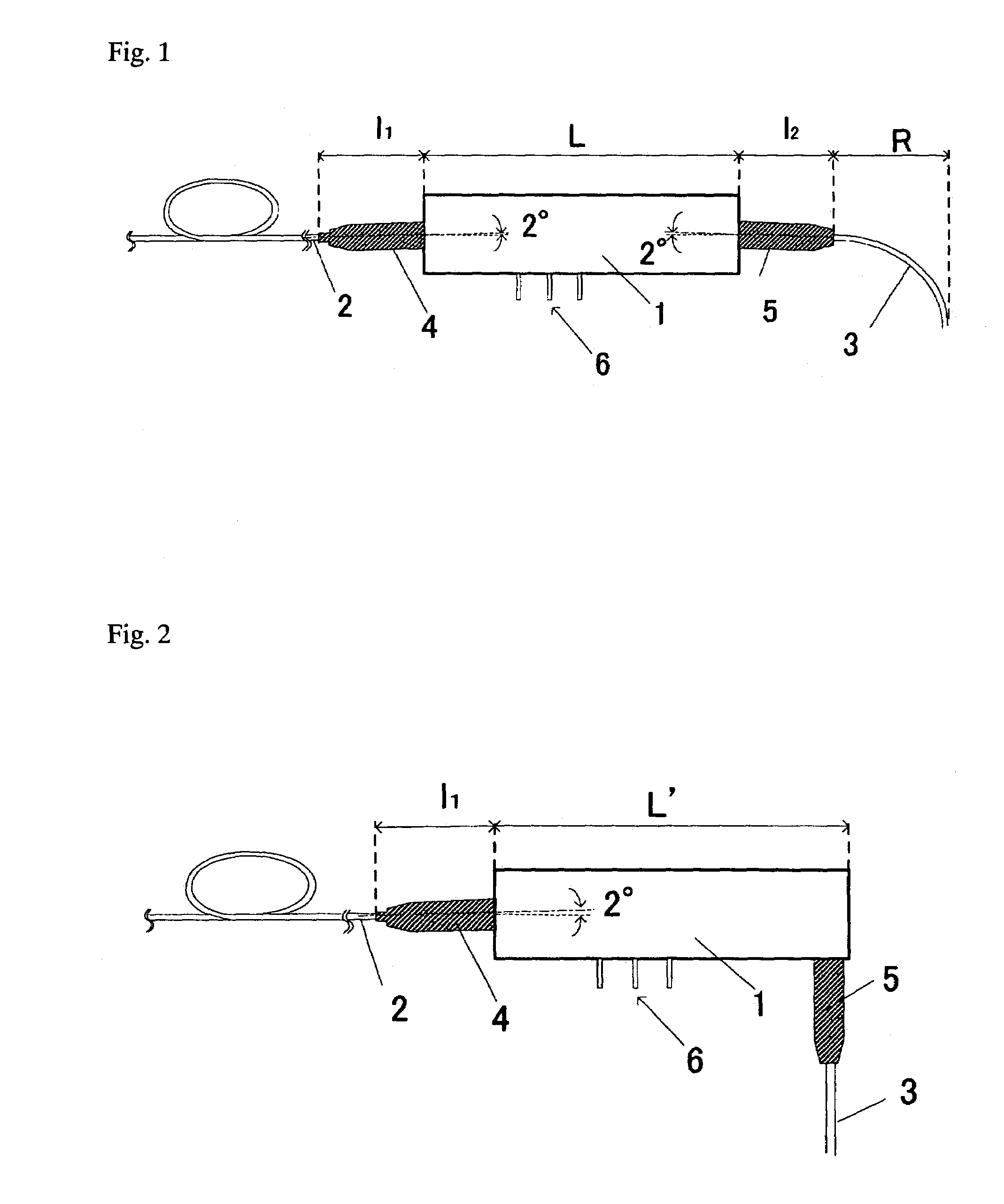
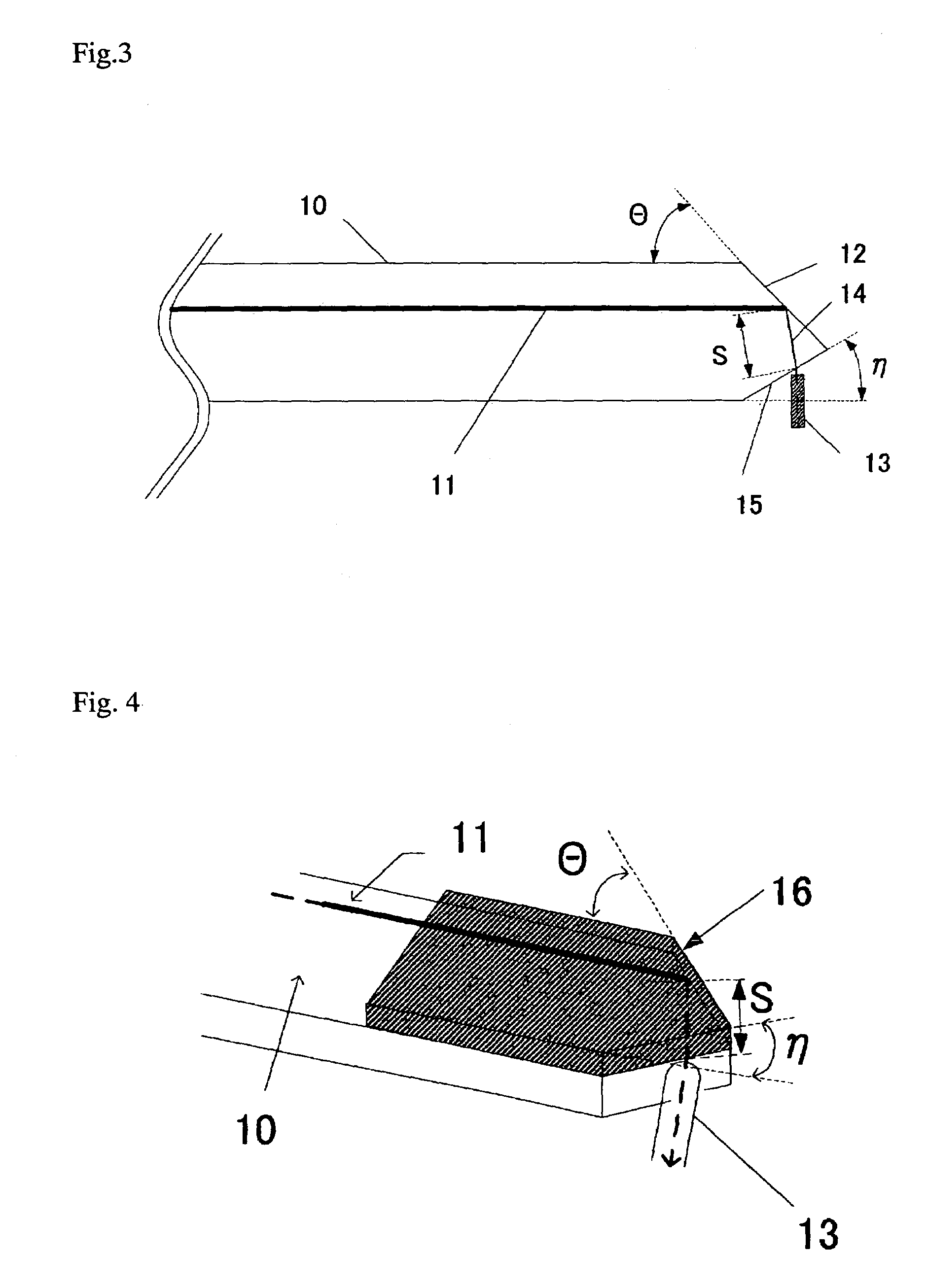
[0012]The invention according to claim 1 is provided with a reflective means on a side of the substrate where the optical wave guide is formed, so that the light reflected from this reflective means, or the light that enters the reflective means propagates through the substrate which is optically coupled with optical fiber. As a result, a reflective member, such as a prism, is not required to bend the optical axis 90°, unlike the prior art, and it becomes possible to achieve the miniaturization of the optical wave guide element in a simple configuration where optical fiber is simply connected to the substrate.
[0025]Furthermore, in the case where a wave guide is provided between the above described reflective means and the optical fiber, adjusting the angle between the reflective means and this wave guide is extremely difficult, causing an increase in the loss of the light waves that propagate through the wave guide. The present invention prevents such a wave guide from being formed and therefore, manufacturing the optical wave guide element is easy, and it is possible to restrict an increase in the loss of light waves.

Problems solved by technology

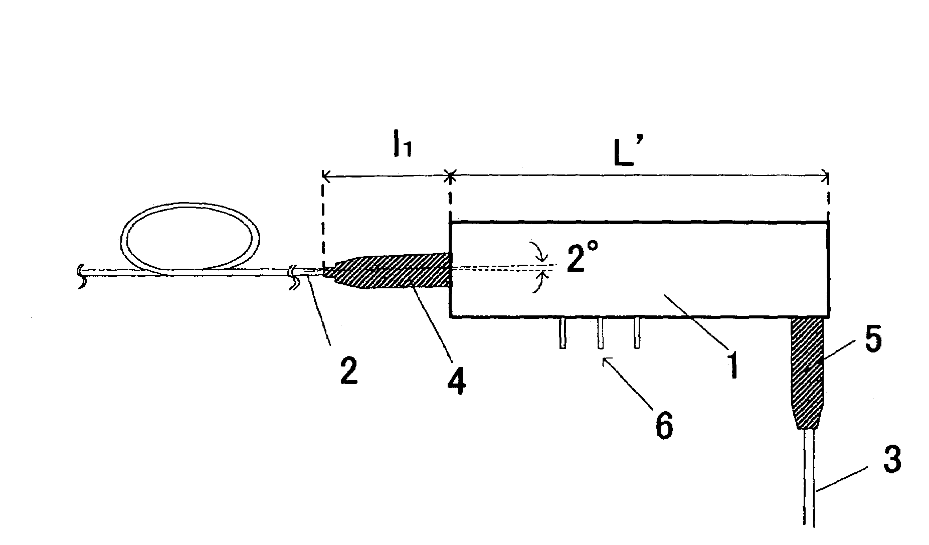
Furthermore, when method (2) is used, the length L′ of the case becomes long in the same manner as in method (1) in order to secure the space for containing the reflective member, and in addition, the manufacturing process becomes complicated because the optical positions must be adjusted and, therefore, method (2) is defective in that manufacturing becomes difficult.

Method used


Image

  • Optical wave guide element, and manufacture therefor
  • Optical wave guide element, and manufacture therefor
  • Optical wave guide element, and manufacture therefor

Examples


Embodiment Construction

[0039]In the following, the preferred embodiments of the present invention are described in detail.

[0040]Here, though an optical modulator is illustrated as an optical wave guide element in the following embodiments, the present invention is not limited to the optical modulator, but rather, it is possible to apply the present invention to an electric field sensor element, or the like, for an optical electric field sensor system. In addition, the optical modulator module is not limited to containing only an optical wave guide element, but rather, it is possible for the module to also contain a light source, such as a semiconductor laser, and a variety of optical parts or electronic parts, such as a light receiving element.

[0041]The substrate where the optical wave guide element is formed is made of a material having the electro-optic effect, such as lithium niobate (LiNbO3; hereinafter referred to as LN), lithium tantalite (LiTaO3), PLZT (lead lanthanum zirconate titanate) or a quart...


PUM


Abstract

An object of the present invention is to provide an optical wave guide element for making the miniaturization of the entire device including the optical wave guide element possible, by connecting optical fiber for incoming and outgoing radiation to the optical wave guide element, so that the optical wave guide element and the optical fiber are positioned at an angle of 90°, as well as to provide a manufacturing method for the same.

Description

BACKGROUND OF THE INVENTION[0001](1) Field of the Invention[0002]The present invention relates to an optical wave guide element wherein an optical wave guide is formed on a substrate having the electro-optic effect and the manufacture of the same, in particular, to an optical wave guide element characterized by the connection structure of a substrate having the electro-optic effect to optical fiber and the manufacture of the same.[0003](2) Related Art Statement[0004]A dense wavelength division multiplexing (DWDM) technology has been developed for optical communication systems corresponding to an increase in the demand for high speed, large capacity data communication systems in recent years. As a result, it becomes necessary to utilize the systems by combining a great number of optical wave guide elements, such as optical modulators, and in particular, miniaturization of the bodies of these optical wave guide elements and the connection structures of the bodies to optical fiber is r...

Claims


Application Information

Patent Timeline
IPC IPC(8): G02B6/26G02B6/34G02B6/12G02B6/30G02B6/42G02F1/035
CPCG02B6/30G02B6/4214G02B2006/12104
Inventor SAITOU, TSUTOMU
Owner SUMITOMO OSAKA CEMENT CO LTD
Learn More