Compact multiple-frequency Z-type inverted-F antenna

a multi-frequency z-type, inverted-f technology, applied in the structure of resonant antennas, resonant antennas, particular array feeding systems, etc., can solve the problems of poor gain performance and difficult to reproduce accurately, and achieve improved gain, simple connection, and improved impedance matching

Active Publication Date: 2007-09-04
WISTRON NEWEB
View PDF12 Cites 39 Cited by
  • Summary
  • Abstract
  • Description
  • Claims
  • Application Information

AI Technical Summary

Benefits of technology

[0006]It is therefore a primary objective of the claimed invention to disclose an omni-directional, planar multiple-frequency Z-type Inverted-F antenna of small size and improved gain, at a reduced cost, and with increased durability, repeatability, and reliability to solve the above stated problems.
[0008]An array of antennas is also disclosed to further enhance gain. Such an array includes a plurality of antennas according to the claimed invention formed on a single dielectric substrate. All radiating traces are formed on one side of the substrate and all ground traces are formed on the other side of the substrate, such that the substrate lies in-between the layer of radiating traces and the layer of ground traces. A conductive strip electrically connects the feed points of adjacent antennas, and a ground strip connects the ground areas of adjacent antennas, allowing simple connection of all antennas in the array with a single feeding cable.
[0009]The claimed multiple-frequency antenna utilizes a wedge-shaped components structure that enables better impedance matching and demonstrates better bandwidth characteristics in a compact multiple-frequency antenna. A printed circuit is utilized for components giving high repeatability and reliability. Excellent omni-directional radiation patterns, high gain performance, and a wide impedance or VSWR bandwidth is achieved.

Problems solved by technology

Although many designs have been presented to solve these problems, they are still of a relatively large size, difficult to reproduce accurately, highly directional, suffer poor gain performance, especially in the 5 GHz area range, and / or offer narrow Voltage Standing Wave Ratio (VSWR) bandwidths amongst the frequencies.

Method used


Image

  • Compact multiple-frequency Z-type inverted-F antenna
  • Compact multiple-frequency Z-type inverted-F antenna
  • Compact multiple-frequency Z-type inverted-F antenna

Examples


Embodiment Construction

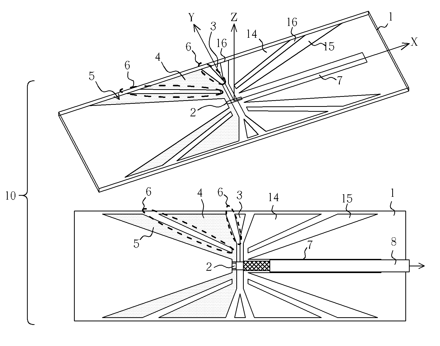
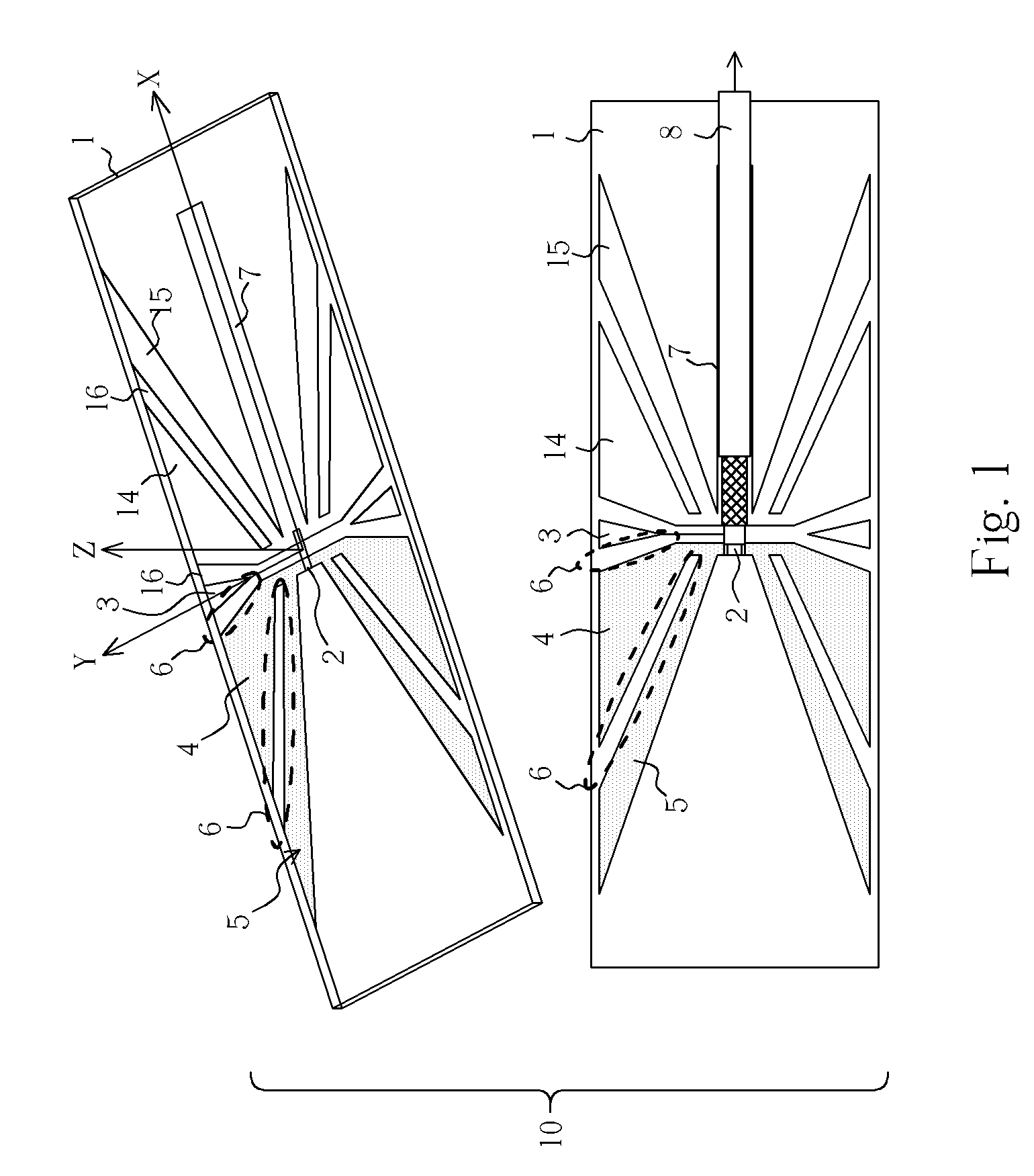
[0018]Please refer to FIG. 1 illustrating a multiple-frequency antenna 10 according to the present invention. The antenna 10 is formed, preferably printed, on a dielectric substrate 1 having a horizontal axis and a vertical axis perpendicular to the horizontal axis. Although horizontal and vertical are perspective terms, here they are intended to mean, in the case of the bottom portion of FIG. 1, the horizontal axis extends left and right across the substrate 1 and the vertical axis extends up and down across the substrate 1. Substrate size is not to be considered limiting but is suggested to be approximately 50 mm by 17 mm to achieve best results.

[0019]A feed point 2 is disposed along the horizontal axis to the left of the vertical axis and is part of a feeding area shown as the small rectangular strip formed parallel with, and to the left of the vertical axis. A variable ground strip 7 is formed along the horizontal axis on the right side of the vertical axis opposite from the fee...


PUM


Abstract

A compact multiple-frequency Z-type Inverted-F antenna includes a dielectric substrate having a horizontal axis and a vertical axis perpendicular to the horizontal axis. A feed point is disposed along the horizontal axis on a first side of the vertical axis and a ground strip is disposed along the horizontal axis on a second side of the vertical axis opposite the feed point. A plurality of wedge-shaped radiating traces is arranged symmetrically with respect to the horizontal axis and disposed on the first side of the vertical axis. A plurality of wedge-shaped ground traces symmetrical to the plurality of radiating traces with respect to the vertical axis are disposed on the second side of the vertical axis.

Description

BACKGROUND OF THE INVENTION[0001]1. Field of the Invention[0002]This invention relates generally to antennas and more specifically to the structure of a multiple-frequency Z-type Inverted-F antenna of small size and improved gain.[0003]2. Description of the Prior Art[0004]Following the consumer driven trend towards smaller wireless communications devices, there is an ongoing need of increased miniaturization and increased functionality of antennas. Aside from manufacturing and assembly concerns, complicating the design process is the additional necessity of good gain performance for each of two or more frequencies, each having omni-directional radiation patterns, for convenient and reliable transmission and reception in today's wireless world.[0005]Although many designs have been presented to solve these problems, they are still of a relatively large size, difficult to reproduce accurately, highly directional, suffer poor gain performance, especially in the 5 GHz area range, and / or ...

Claims


Application Information

Patent Timeline
Patent Type & Authority Patents(United States)
IPC IPC(8): H01Q1/38H01Q9/16
CPCH01Q1/24H01Q1/38H01Q5/371H01Q21/0006H01Q9/285
Inventor TSAI, FENG-CHI EDDIE
Owner WISTRON NEWEB
Why Eureka
Try Eureka