Method and apparatus for acoustic source tracking using a horizontal line array

a technology of acoustic source and a horizontal line array, which is applied in direction/deviation determination systems, instruments, systems with undesired wave elimination, etc., can solve the problems of reducing the detection accuracy of acoustic signals, severely degrading the performance, and not being able to assume the good assumption of underwater acoustic signals, so as to achieve the effect of greatly reducing the inability to remove interference signals

Inactive Publication Date: 2007-09-04
USA AS REPRESENTED BY THE SEC OF THE NAVY THE
View PDF5 Cites 13 Cited by
  • Summary
  • Abstract
  • Description
  • Claims
  • Application Information

AI Technical Summary

Problems solved by technology

In an ocean environment, particularly in shallow water, many interference sources, e.g., loud surface ships, are present, interfering with the detection and directional finding of a target signal.
The existing processing techniques have difficulty in achieving these two goals when the source is moving.
However, in practice, source motion severely degrades the performance as discussed below.
While this assumption is widely accepted for radar signal processing, it is not a good assumption for underwater acoustic signals.
However, no range information is available using plane wave beamforming.
Conversely, lack of adequate environmental information presents a major obstacle in applying this processing to the real world data.
The mismatch between the model and the real world can result in poor performance, such as erroneous estimation of the source range.
For a moving source, mismatch can result in large scatters in range estimates, causing ambiguities and incorrect range tracking.
As mentioned above, in an ocean environment, particularly in shallow water, many loud surface ships are present, interfering with the detection and directional finding of a target signal.
If the objective is to detect a weak source in the background of high noise or many interfering signals such as that produced by merchant ships, conventional beamforming for a horizontal line array is inadequate because of its wide beam width and high sidelobe levels.
For passive acoustic source detection in an ocean waveguide, adaptive array processing suffers from a mismatch between a plane wave signal model and the real signal.
In practice, however, the true covariance matrix is not known and must be estimated from the data.
When the target and interference sources are moving, as often is the case, the non-stationariness of the acoustic environment limits the number of data samples (i.e., snapshots) available for estimating the covariance matrix, resulting in a “snapshot-deficient” condition.
The performance degradation is worse as the array aperture increases, thus defeating the purpose of a large aperture HLA.
The MVDR processor will suffer a severe beam power degradation under the snapshot deficient condition.
The amount of beam power loss increases with the number of sensors on the array.
However, in the practical sonar world, this condition is rarely met for a large aperture horizontal line array when the source or the interferer is moving.
A remedy is to limit the signal loss using the white noise constraint, but the performance is severely degraded compared with the stationary source / interferers case.
One problem is the non-stationariness due to target / interferer motion, creating a snapshot deficient condition.
This function is severely limited by the snapshot-deficient condition.
The other problem is lack of robustness in target range estimation and tracking.
When environmental acoustic information are lacking or are inaccurate, the results are erroneous, thereby effectively voiding the use of a large aperture array for source localization.

Method used


Image

  • Method and apparatus for acoustic source tracking using a horizontal line array
  • Method and apparatus for acoustic source tracking using a horizontal line array
  • Method and apparatus for acoustic source tracking using a horizontal line array

Examples


Embodiment Construction

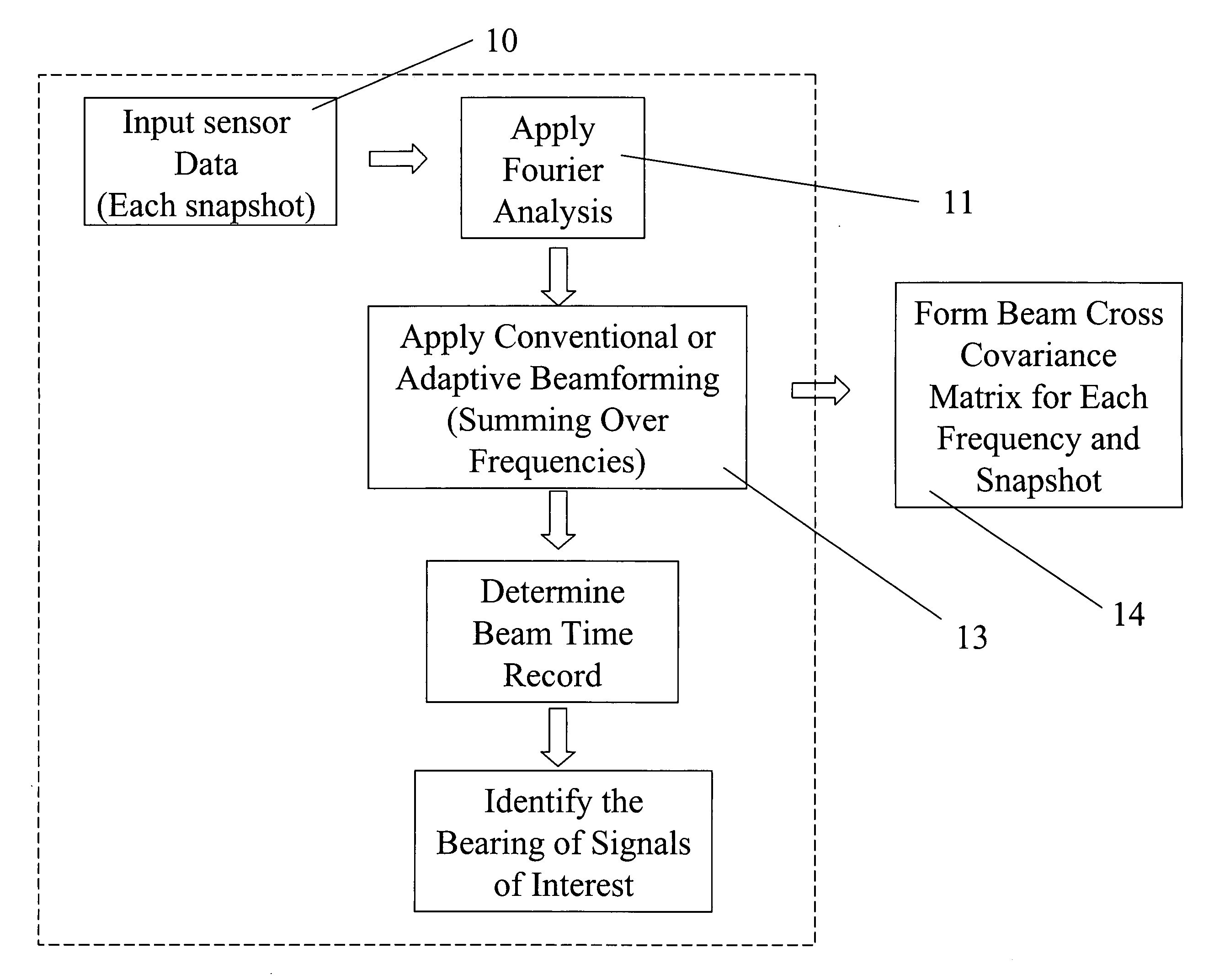
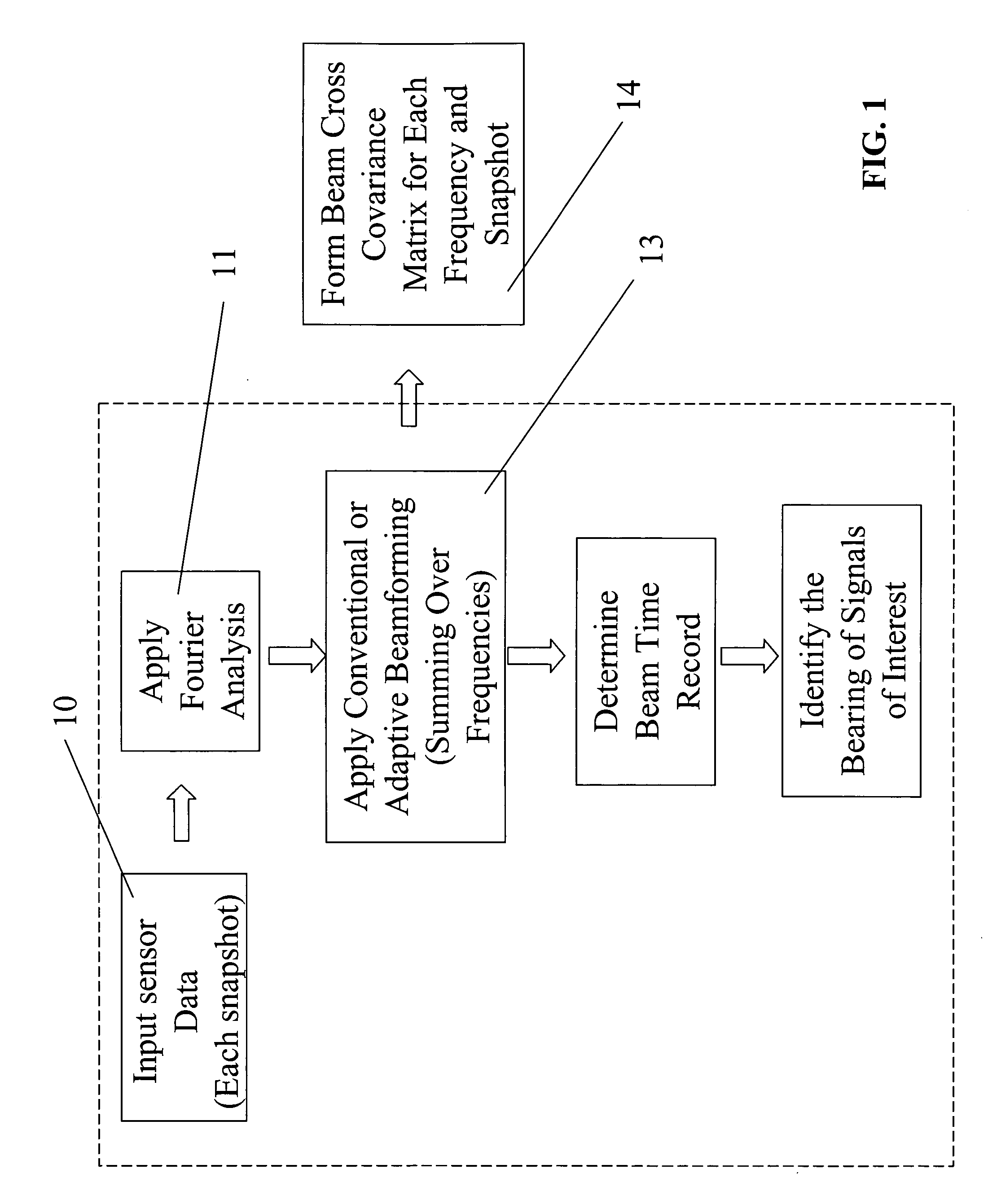
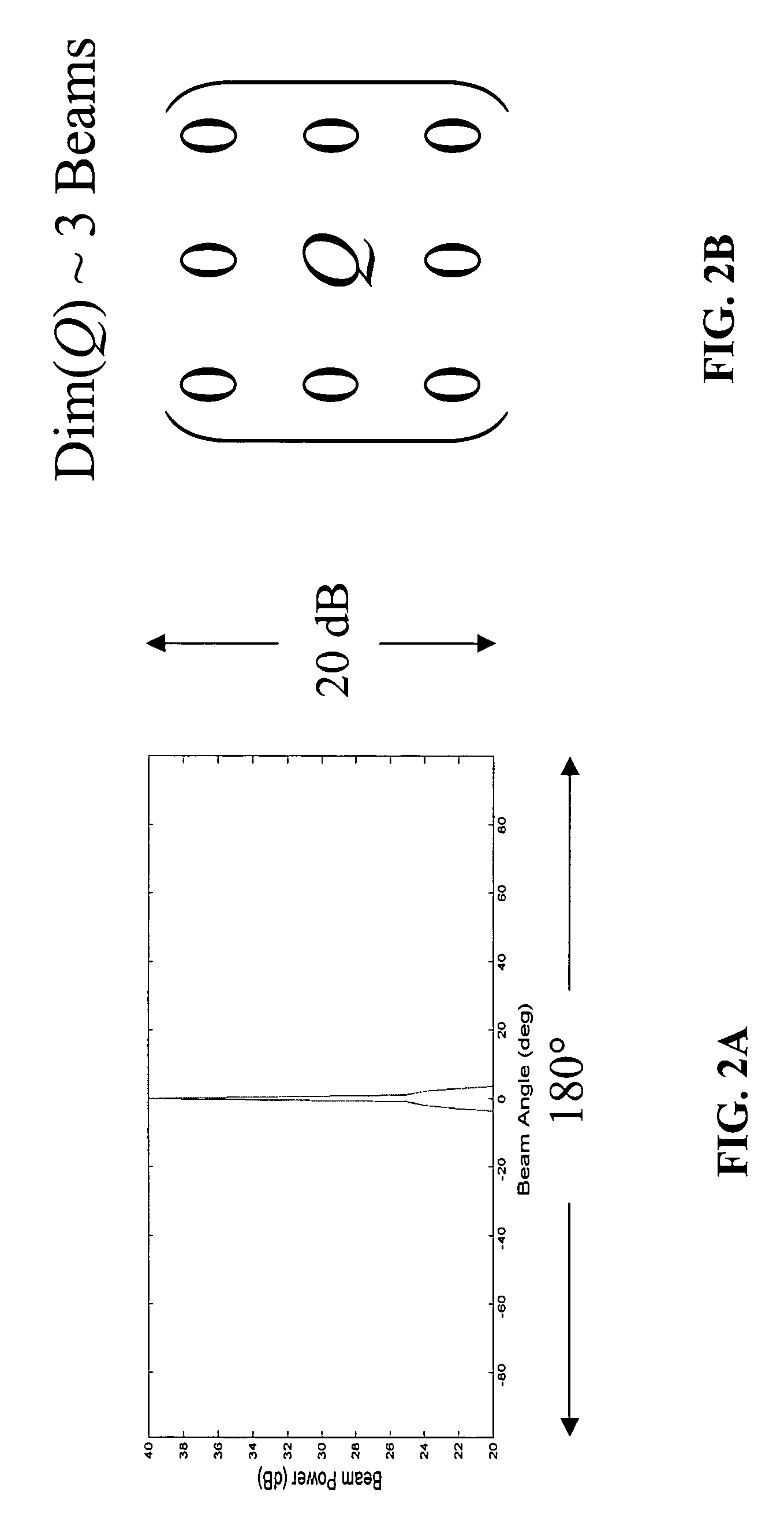
[0045]For motion compensation and / or environment-independent source tracking, an embodiment of the instant invention, for example, processes broadband signals in the beam domain. When the signal and interference field occupy different beams, the motion will spread the beam covariance eigenvalue spectrum from one to two (or even three) eigenvalues, but the eigenvalues and eigenvectors of the signal and interference remain in two separate beam sub-spaces centered on the signal and interference bearings. For a source changing bearing, motion effect can be compensated by integrating over the signal beam covariance matrix (i.e., the beam covariance sub-matrix in the signal space) that synchronizes with the source bearing-rate. For a source changing range, elements of the signal beam covariance matrix have the same range and frequency dependence as predicted by the wave-guide invariant theory. The source range-change can be compensated by, for example, frequency-change (i.e., shift). Usin...


PUM


Abstract

An apparatus for processing passive acoustic signals received on a horizontal line array that were either emitted from an underwater object or echo returned from an object, is proposed to track the motion (bearing change and range change) of an object (target) relative to the receiver horizontal line array. Adaptive array processing for a moving object is biased for a moving source when the number of data samples is limited by the stationariness condition. Motion compensation can be carried out in the beam domain by beam shifting for a bearing changing object and frequency shifting for a range changing object. The method includes receiving acoustic signals from the target, determining the beam covariance matrices, determining the target bearing rate and range rate, processing the beam covariance matrices by compensating for the target motion, and producing a beam power plot versus time. Interference signal is suppressed when the interference source does not have the same motion (bearing and range rate) as the target. The method does not need detailed environmental acoustic information of the sound channel normally required to model the sound propagation.

Description

TECHNICAL FIELD[0001]This invention relates to a method and apparatus for acoustic source detection and tracking in bearing and range using a large aperture horizontal line array, and more particularly, to a method and apparatus for acoustic source detection and tracking in bearing and range that suppresses interference signals by accounting for spatial asymmetry between source motion and interferer motion.DESCRIPTION OF RELATED ART[0002]Signal processing in underwater acoustics has been centered around the problem of detection and localization of a target or signal in an ocean waveguide. Such detection and localization of a low level acoustic signal (e.g., a quiet target) involves the use of an array of a large number of hydrophones, which enhances the target signal-to-noise (“S / N”) ratio by the array spatial processing gain. The array, for example, includes a horizontal aperture to estimate the signal bearing.[0003]In an ocean environment, particularly in shallow water, many inter...

Claims


Application Information

Patent Timeline
Patent Type & Authority Patents(United States)
IPC IPC(8): G01S3/86
CPCG01S3/808G01S3/86H04R3/005H04R2430/20
Inventor YANG, TSIH C.
Owner USA AS REPRESENTED BY THE SEC OF THE NAVY THE
Why Eureka
Try Eureka