Transparent microporous materials for CMP

a microporous material and cmp technology, applied in the direction of flexible wheel, grinding machine components, manufacturing tools, etc., can solve the problems of unsatisfactory polishing performance, undesirable polishing defects, and constant decrease of optical transmittance during the lifetime of the polishing pad

a microporous material and cmp technology, applied in the direction of flexible wheel, grinding machine components, manufacturing tools, etc., can solve the problems of unsatisfactory polishing performance, undesirable polishing defects, and constant decrease of optical transmittance during the lifetime of the polishing pad

US7267607B2Inactive Publication Date: 2007-09-11CMC MATERIALS INC

Image

  • Transparent microporous materials for CMP
  • Transparent microporous materials for CMP
  • Transparent microporous materials for CMP

Examples


example 1

[0039]Typical properties of pad samples given in Table 1 were produced from extruded TPU sheets with a solid sheet density of 1.2 g / cc with resin hardness of 72 Shore D, sheet thickness of 58 mils, saturation CO2 pressure of 5 MPa, saturation time of 40 hours, CO2 desorption time of 3 minutes and foaming time of 2 minutes. Foaming temperatures of 106° C. and 111° C. were used for sample A and B, respectively. The amount of CO2 used to foam each sheet was 43 mg CO2 / g of polymer for sample A and 53 mg CO2 / g of polymer for sample B.

[0040]

TABLE 1Pad PropertiesShoreρp% R / TgSampleA(g / cc)ρp / ρsCell Size (μm)% C(° C.)A96.50.98883%0.5 μm ± 0.28 μm0.0644B95.50.85071%1.4 μm ± 1.2 μm 0.0846

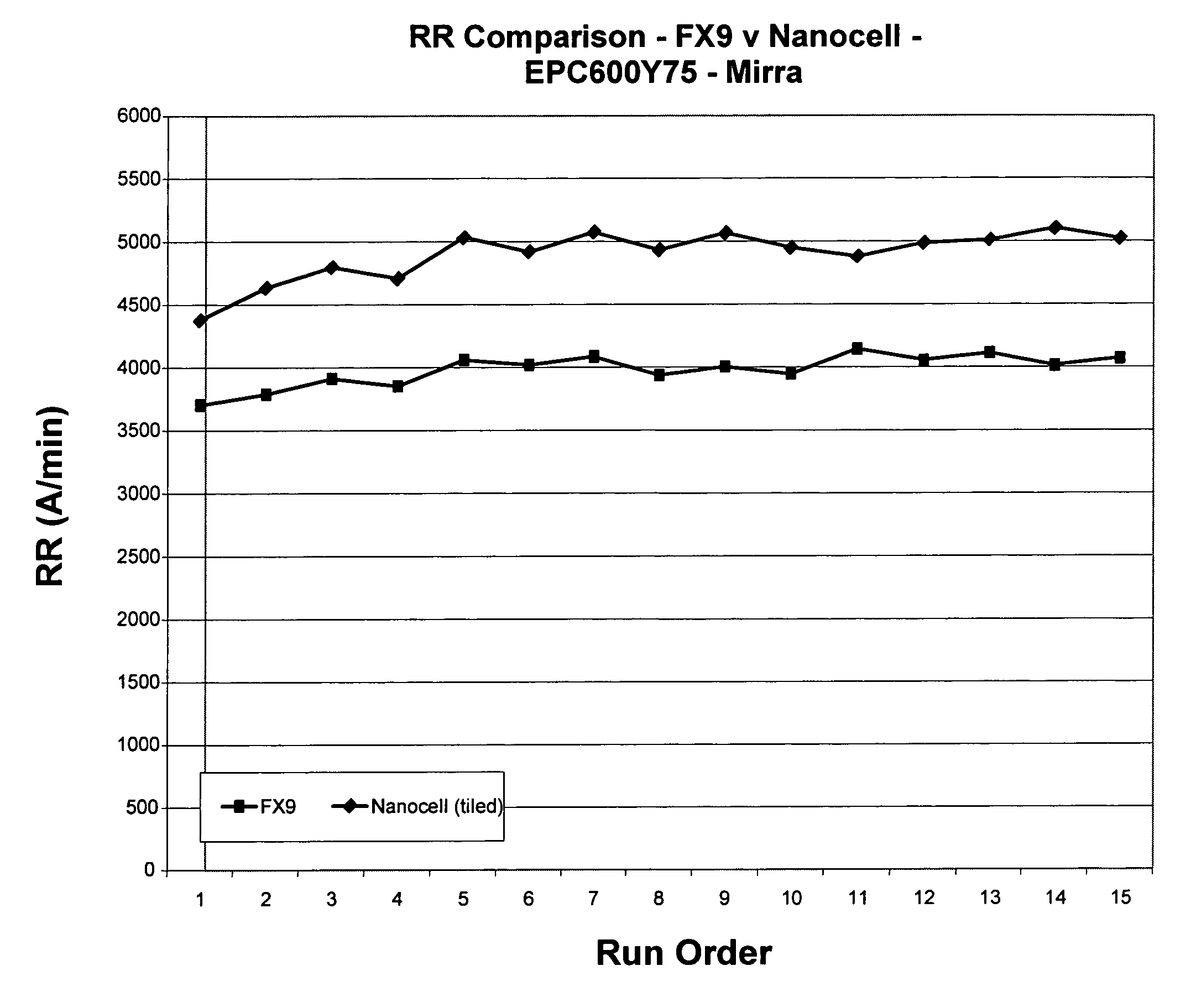
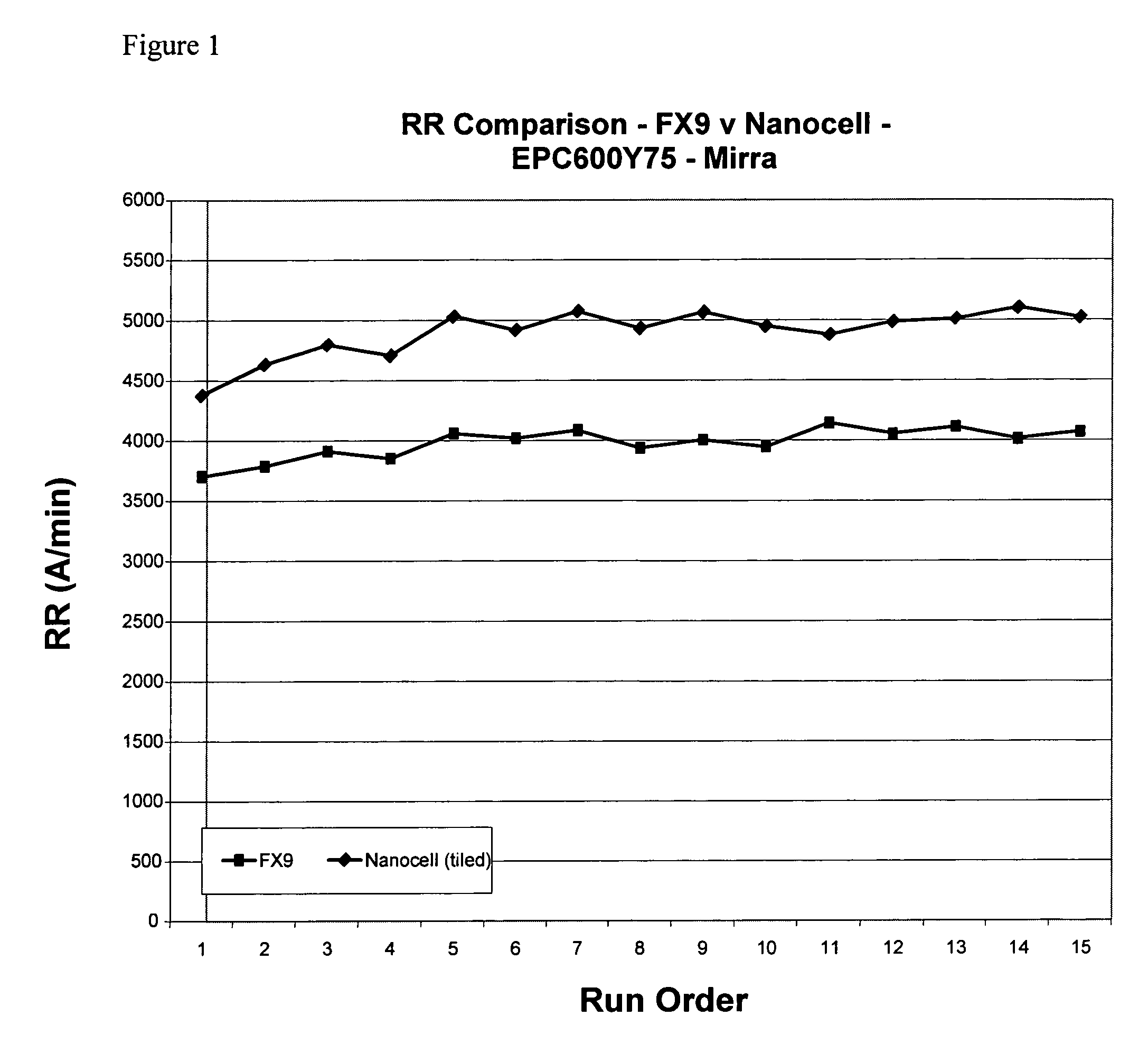
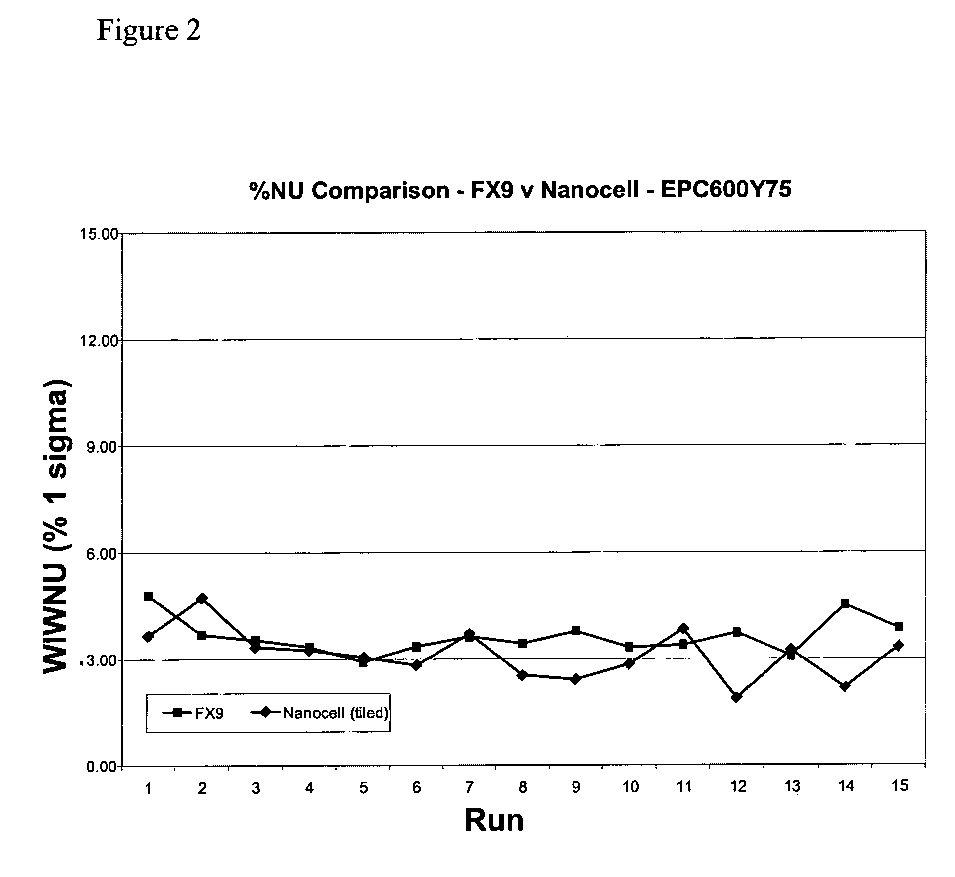
[0041]A copper polishing comparison test between a commercially available pad (Freudenberg FX-9) with the sample A pad of the present invention was performed using a 20 inch (508 cm) diameter pad with subpad and x-y grooves on a Mirra polisher. As shown in FIGS. 1 and 2, the sample A pad of the present inventi...


PUM

PropertyMeasurementUnit
pore sizeaaaaaaaaaa
average cell sizeaaaaaaaaaa
densityaaaaaaaaaa

Abstract

The invention is directed to a chemical-mechanical polishing pad substrate comprising a microporous closed-cell foam characterized by a narrow pore size distribution in the range of about 0.01 microns to about 10 microns. The polishing pad is produced by foaming a solid polymer sheet with a supercritical gas under an elevated temperature and pressure until the sheet is saturated with gas. The invention is further directed to a polishing pad comprising the polishing pad substrate, a method of polishing comprising the use of the polishing pad substrate, and a chemical-mechanical apparatus comprising the polishing pad substrate.

Description

CROSS-REFERENCE TO RELATED APPLICATIONS[0001]This application is a continuation-in-part of application Ser. No. 10 / 282,489, filed Oct. 28, 2002, which is hereby incorporated by reference.FIELD OF THE INVENTION[0002]This invention pertains to a chemical-mechanical polishing pad substrate comprising a microporous closed-cell foam characterized by a narrow pore size distribution.BACKGROUND OF THE INVENTION[0003]Chemical-mechanical polishing (“CMP”) processes are used in the manufacturing of microelectronic devices to form flat surfaces on semiconductor wafers, field emission displays, and many other microelectronic substrates. For example, the manufacture of semiconductor devices generally involves the formation of various process layers, selective removal or patterning of portions of those layers, and deposition of yet additional process layers above the surface of a semiconducting substrate to form a semiconductor wafer. The process layers can include, by way of example, insulation l...

Claims


Application Information

Patent Timeline
11 Sep 2007
Publication
US7267607B2
IPC
B24B5/00; B24D11/00; B24B1/00; B24B29/00; B24B49/12; B24D7/12; H01L21/304
CPC
B24B37/24; B24D3/32; B24D13/12; H01L21/304
Inventors
PRASAD, ABANESHWAR