Rapid flow fractionation of particles combining liquid and particulate dielectrophoresis

a technology of dielectrophoresis and fractionation, which is applied in the direction of fluid pressure measurement, liquid/fluent solid measurement, peptide measurement, etc., can solve the problem that force cannot be exploited

Inactive Publication Date: 2007-09-11
UNIVERSITY OF ROCHESTER
View PDF5 Cites 58 Cited by
  • Summary
  • Abstract
  • Description
  • Claims
  • Application Information

AI Technical Summary

Benefits of technology

[0008]There are clear functional advantages when fluidic and particulate control can be combined in one microsystem.
[0012]It has been demonstrated that the DEP effect can be harnessed to move and dispense small volumes of liquid containing suspensions of particles in the submicron or nanometer range and that these particles can be simultaneously separated based on their size or dielectric properties. The separation occurs because the downward-directed, positive DEP force imposed by the nonuniform electric field within the liquid attracts the larger particles more strongly, leaving the smaller particles to be swept further along in the shear flow of the finger. Using two-color fluorescence microscopy, the separation of two size cuts of polystyrene beads, viz, 0.53 and 0.93 μm diameter, is easily discerned. The process is rapid, usually requiring ˜102 ms for a structure 6 mm in length.
[0013]A simple model is presented for the separation scheme, and simulations performed with this model correlate best to the experimental data using Re[K(ω)]˜0.5 (as will be explained in detail below), which is slightly below the expected range of 0.8-1.0. The use of frequency as a control parameter for transient particle separation may facilitate gradient deposition of particles within monodisperse populations based on medically important attributes.

Problems solved by technology

At the lower frequencies used for electrowetting, this force cannot be exploited because the electric field is blocked from the interior of the liquid if the electrodes are dielectric coated.

Method used


Image

  • Rapid flow fractionation of particles combining liquid and particulate dielectrophoresis
  • Rapid flow fractionation of particles combining liquid and particulate dielectrophoresis
  • Rapid flow fractionation of particles combining liquid and particulate dielectrophoresis

Examples


Embodiment Construction

[0022]A preferred embodiment will be set forth in detail with reference to the drawings, in which like reference numerals refer to like elements throughout.

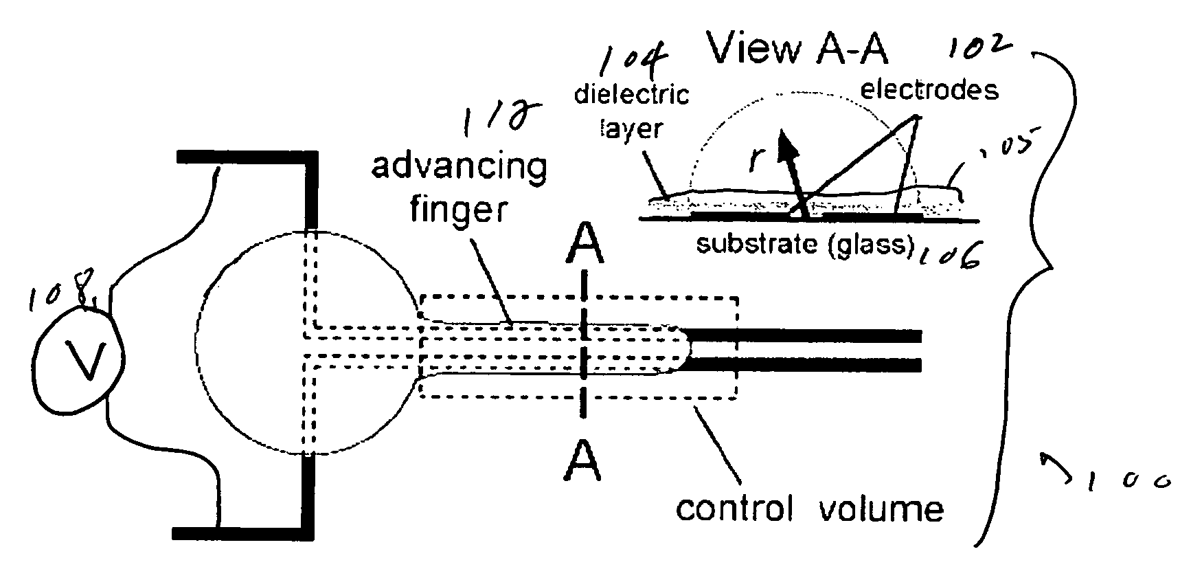
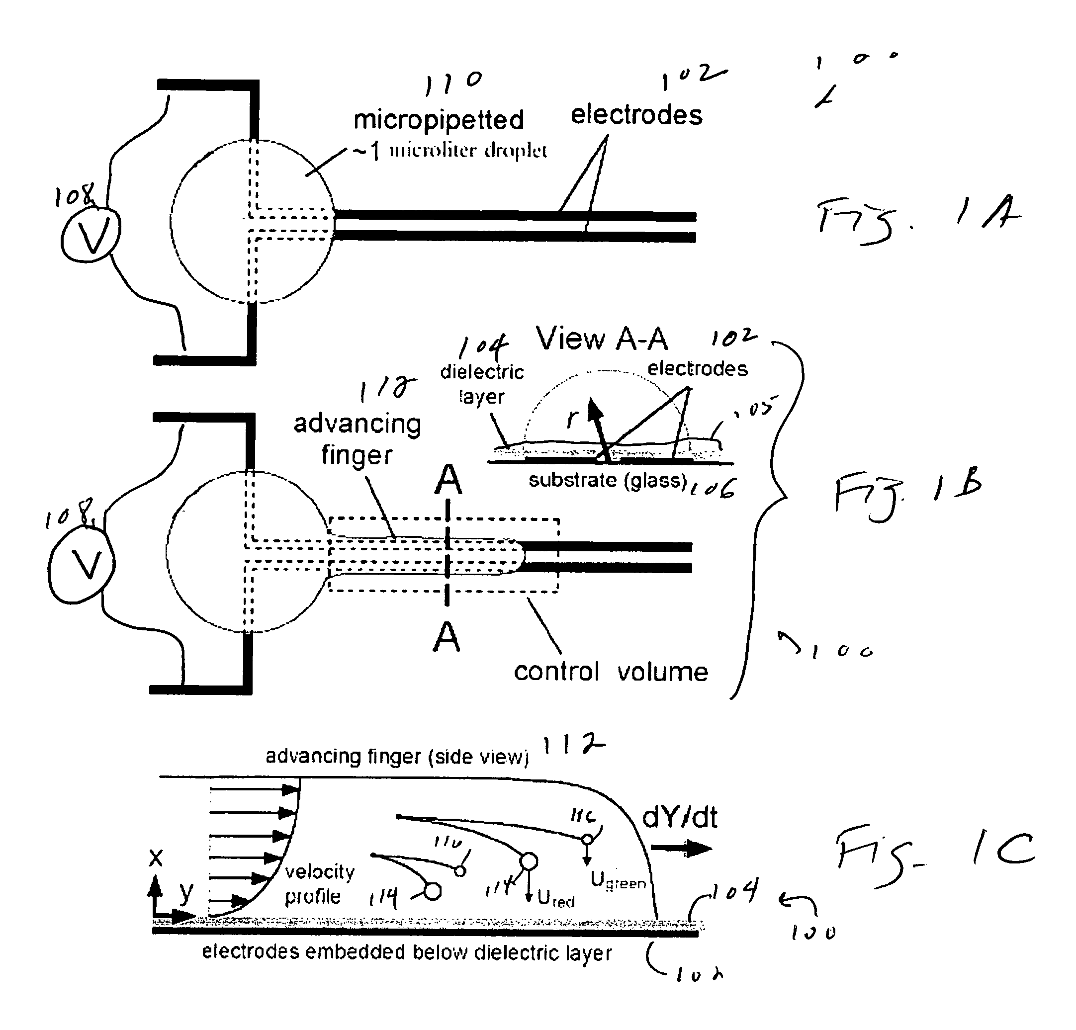
[0023]FIG. 1A shows the planar electrode structure 100 used in the experiments. The parallel electrode strips 102, patterned in 2 kÅ thick Al evaporatively deposited on borosilicate glass substrates 106, were of width w=20 μm, separation g=20 μm, and length=6 mm. These structures were spin-coated, first with ˜2 μm of SU-8™, an epoxy-based, dielectric material, to form a dielectric layer 104, and then with ˜0.5 μm of photoresist 105 (Shipley 1805) to control wetting. The electrodes 102 are connected to a voltage source 108.

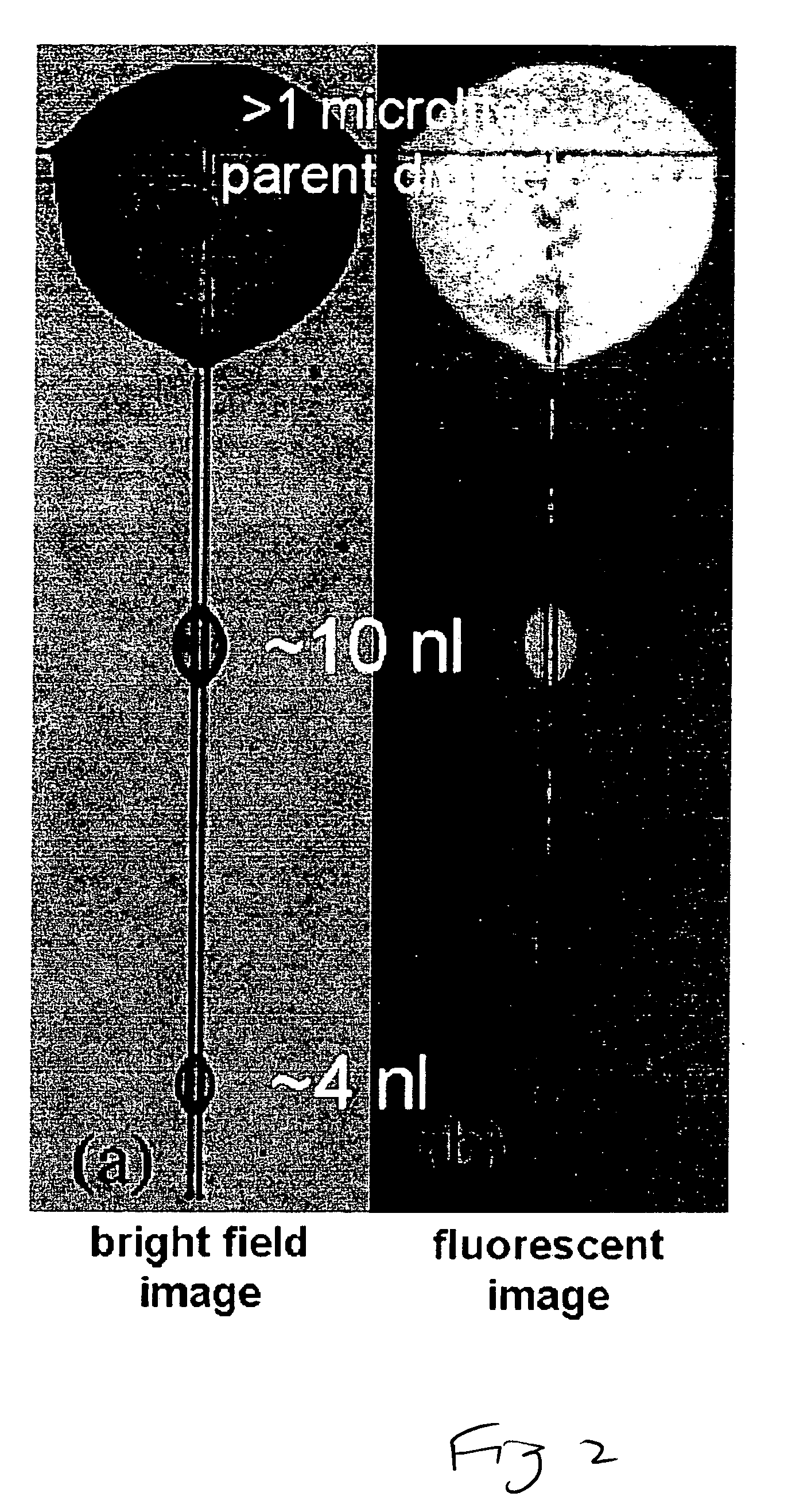
[0024]To facilitate quantitative investigation of the separation effect, we suspended fluorescent-labeled, polystyrene microspheres (0.53 and 0.93 μm diameter, 0.06% by volume; Bangs Labs, Fishers, Ind.) in deionized water, adding nonionic surfactant to prevent particle aggregation (Tween 20, 0.1%-0.5% by volume...


PUM

PropertyMeasurementUnit
heightaaaaaaaaaa
heightaaaaaaaaaa
volumesaaaaaaaaaa

Abstract

Rapid, size-based, deposition of particles from liquid suspension is accomplished using a nonuniform electric field created by coplanar microelectrode strips patterned on an insulating substrate. The scheme uses the dielectrophoretic force both to distribute aqueous liquid containing particles and, simultaneously, to separate the particles. Size-based separation is found within nanoliter droplets formed along the structure after voltage removal. Bioparticles or macromolecules of similar size can also be separated based on subtle differences in dielectric property, by controlling the frequency of the AC current supplied to the electrodes.

Description

REFERENCE TO RELATED APPLICATION[0001]The present application claims the benefit of U.S. Provisional Patent Application No. 60 / 591,587, filed Jul. 28, 2004, whose disclosure is hereby incorporated by reference in its entirety into the present disclosure.STATEMENT OF GOVERNMENT INTEREST[0002]The work leading to the present invention was supported by grants from the National Institutes of Health (NIH Grant No. RR16083), the National Science Foundation (NSF Grant No. ECS-0323429), and the Infotonics Technology Center, Inc. (NASA Grant No. NAG3-2744). The government has certain rights in the invention.FIELD OF THE INVENTION[0003]The present invention is directed to the size and / or dielectric separation of particles and more particularly to a technique for size-selective and / or dielectric-sensitive separation of particles which combines liquid and particulate dielectrophoresis.DESCRIPTION OF RELATED ART[0004]Many schemes exploiting electrostatic forces in practical implementations of the...

Claims


Application Information

Patent Timeline
Patent Type & Authority Patents(United States)
IPC IPC(8): G01N27/447
CPCB03C5/005B03C5/026
Inventor KING, MICHAEL R.LOMAKIN, OLEGJONES, THOMAS B.AHMED, RAJIB
Owner UNIVERSITY OF ROCHESTER
Why Eureka
Try Eureka