
Ceramic metal halide lamp

a ceramic metal halide and lamp body technology, applied in the field of electric lamps, can solve the problems of low temperature, premature failure of lamps, and particularly harmful water vapor, and achieve the effect of good color rendering and high efficiency

Inactive Publication Date: 2007-09-11
GENERAL ELECTRIC CO
View PDF25 Cites 15 Cited by
  • Summary
  • Abstract
  • Description
  • Claims
  • Application Information

AI Technical Summary

Benefits of technology

"The patent describes a ceramic metal halide lamp with an improved fill that includes an inert gas, mercury, and a halide component. The halide component includes at least 5 mol% of sodium halide, optionally from 1% to 10% of a group IIIA metal halide, from 10% to 95% of an alkaline earth metal halide, and optionally from 1% to 15% of a rare earth metal halide. The lamp has a wall loading of at least 30 W / cm2 when energized. The technical effects of this design include improved performance, lumen maintenance, and the ability to select color rendering properties of the lamp."

Problems solved by technology

However, premature failure of the lamps may occur due to blackening of the discharge vessel walls.
Water vapor is particularly harmful because even trace amounts increase the evaporation of the tungsten filament coil by means of the well-known “water cycle.” In the water cycle, the temperature of the tungsten coil is thermally sufficient to decompose water vapor into hydrogen and oxygen.
Lamps that operate at low wall loadings (WL), e.g., below about 30 W / cm2, and thus low temperatures, i.e. below about 200° C. interior wall temperatures, generally do not support the tungsten halogen cycle.
Additionally, if WL is too low then the halide temperature tends to be too low leading to reduced halide vapor pressure and reduced performance.

Method used


Image

  • Ceramic metal halide lamp
  • Ceramic metal halide lamp
  • Ceramic metal halide lamp

Examples


example

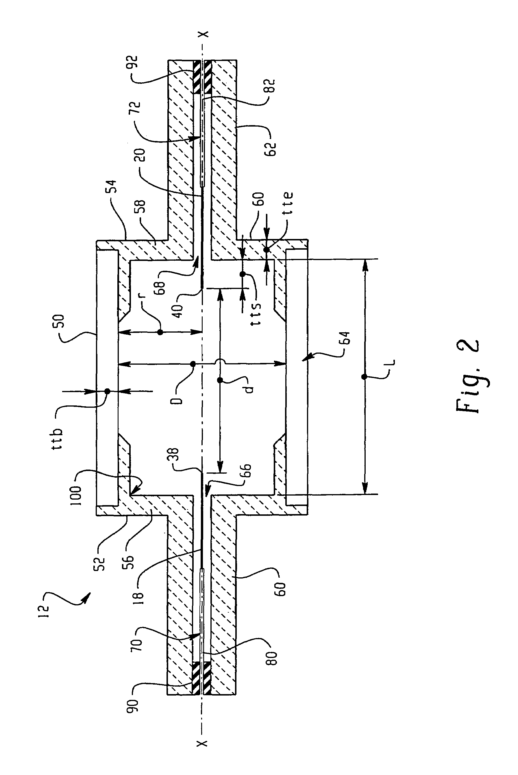
[0054]Arctubes are formed according to the shape shown in FIG. 2 from three component parts. The internal diameter D is ˜5.8 mm and the internal length L is ˜7.6 mm. A fill comprising ˜5 mg halide in the weight ratios given in TABLE 1 is used for forming lamps. The metal halide arctubes are back filled with a rare gas, comprising Ar or Xe and a small addition of Kr85. The cold fill pressure is 120-300 Torr. The arctubes are assembled into lamps having an outer vacuum jacket and which are run on 70 W Electronic Ballasts. The arctube leg geometry, leadwire design, seal parameters, and outer jacket are the same for all lamps tested.

[0055]Lamps formed as described above are run in a vertical orientation (i.e., as illustrated in FIG. 3) with the lamp cap positioned uppermost at 70 W. TABLE 1 shows the results obtained after 100 hours. CCX and CCY are the chromaticity X and Y, respectively, on a standard CIE chart. The results are the mean of 10-11 lamps.

[0056]

TABLE 1AlkalineRareAlkalineE...


PUM


Abstract

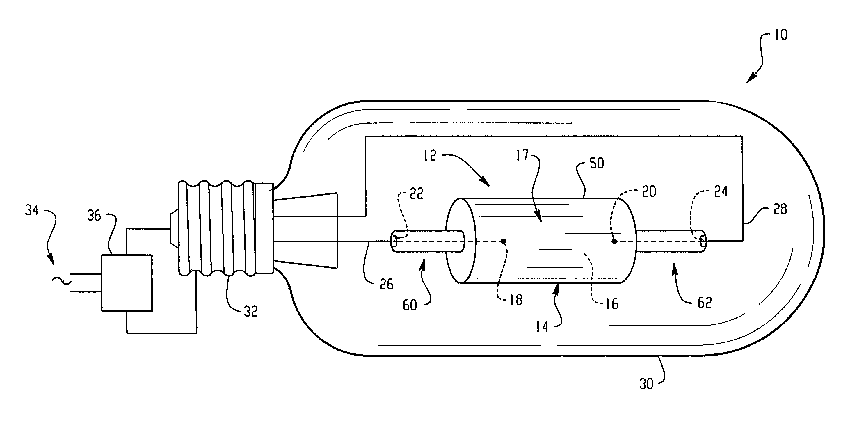
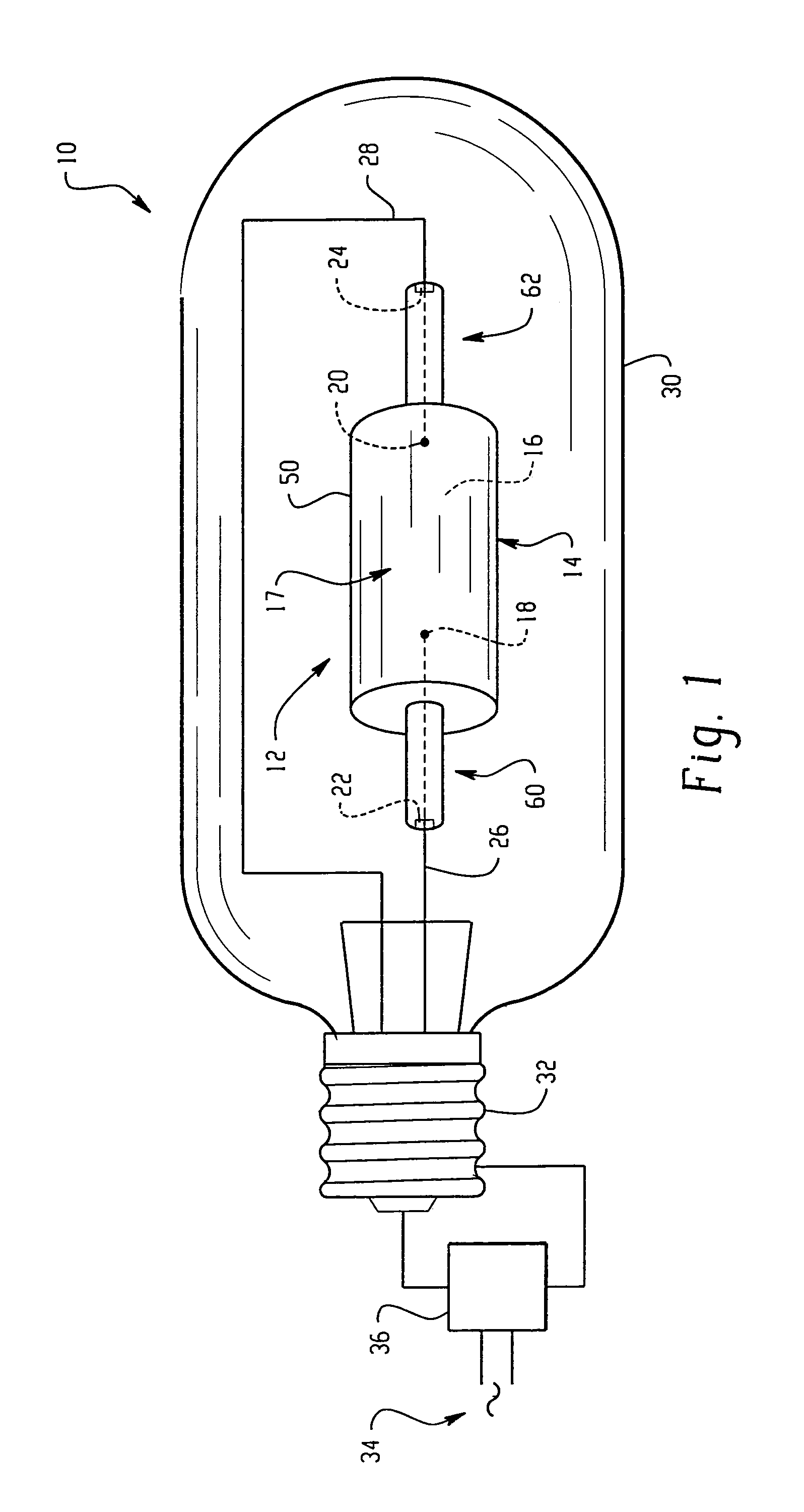
A metal halide lamp (10) includes a discharge vessel (12) which may be formed of a ceramic material. The vessel defines an interior space (16). An ionizable fill (17) is disposed in the interior space. The ionizable fill includes an inert gas, mercury, and a halide component. The halide component includes an alkali metal halide, an alkaline earth metal halide component, and optionally at least one of a rare earth halide and a Group IIIA halide. The alkaline earth metal halide component includes at least one of a barium halide and a strontium halide. At least one electrode (18, 20) is positioned within the discharge vessel so as to energize the fill when an electric current is applied thereto. The lamp having a wall loading, when energized, which is sufficient to maintain an active tungsten halogen cycle.

Description

[0001]This application claims the benefit, as a continuation-in-part, of application Ser. No. 11 / 040,990, filed Jan. 21, 2005, the disclosure of which is incorporated herein in its entirety by reference.BACKGROUND OF THE INVENTION[0002]The present invention relates to an electric lamp with high efficiency, good color rendering, and high lamp lumen maintenance. It finds particular application in connection with a ceramic metal halide lamp with halides of barium or strontium in the fill and will be described with particular reference thereto.[0003]Discharge lamps produce light by ionizing a vapor fill material such as a mixture of rare gases, metal halides and mercury with an electric arc passing between two electrodes. The electrodes and the fill material are sealed within a translucent or transparent discharge vessel which maintains the pressure of the energized fill material and allows the emitted light to pass through it. The fill material, also known as a “dose,” emits a desired ...

Claims


Application Information

Patent Timeline
Patent Type & Authority Patents(United States)
IPC IPC(8): H01J17/20
CPCH01J61/125H01J61/20H01J61/26H01J61/827
Inventor RINTAMAKI, JOSHUA IANKUESTER, PAULPODEVELS, ANDREW
Owner GENERAL ELECTRIC CO
Learn More