
Apparatus and process for irradiating product pallets

a technology of irradiation apparatus and product pallet, which is applied in the field of apparatus and process for irradiating product pallet, can solve the problems that the time between untreated product pallet unloading and reloading on a truck of treated product pallet cannot be reduced below some limit without impairing installation throughput, etc., to achieve the effect of improving throughpu

Inactive Publication Date: 2007-09-25
ION BEAM APPL
View PDF5 Cites 8 Cited by
  • Summary
  • Abstract
  • Description
  • Claims
  • Application Information

AI Technical Summary

Benefits of technology

The present invention is related to an apparatus and process for irradiating products conveyed on a pallet. The apparatus includes a beam source, a shielding wall, and a revolving cylindrical door with at least one recess for holding the pallet. The apparatus can also have means for rotating the pallet during irradiation. The process involves transferring the pallet into the recess in the cylindrical door, irradiating it, and then transferring it out of the recess. The technical effects of the invention include increased throughput and uniform irradiation dose.

Problems solved by technology

Such a shielding is a significant part of the cost of an irradiation apparatus.
When the maze solution is used for bringing products in and out of the irradiation chamber, the maze itself adds to the size and cost of shielding.
The conveyor system for transporting the pallets or carriers across the maze, with many angles, is not only part of the cost of the installation, but also of the time necessary to process products.
Therefore, the time between unload from a truck of an untreated product pallet to reload on a truck of a treated product pallet cannot be reduced below some limit without impairing throughput of the installation.
Moreover, the maintenance of this mechanical device in a high radiation area requires stringent safety measures.
The known rotary disk system allows performing electron-beam irradiation of small packages from above, but is not capable of treating larger packages.
Moreover, irradiation can only be performed from one side, i.e. from above.
A uniform irradiation dose cannot be achieved in these conditions.
However, the concept of a revolving door cannot be derived from this document.

Method used


Image

  • Apparatus and process for irradiating product pallets
  • Apparatus and process for irradiating product pallets
  • Apparatus and process for irradiating product pallets

Examples


first embodiment

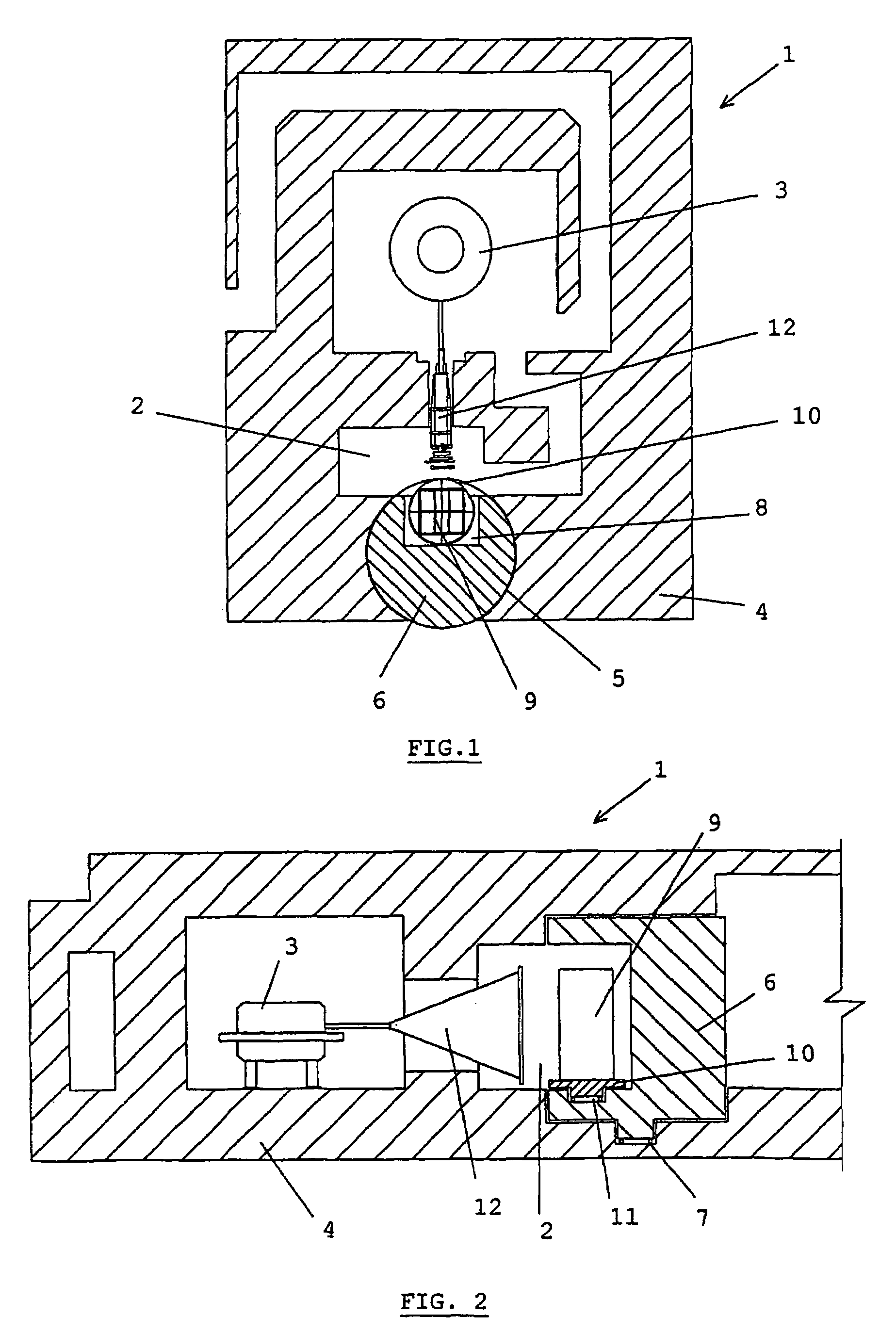
[0044]A preferred first embodiment of the present invention is illustrated on FIGS. 1 and 2.

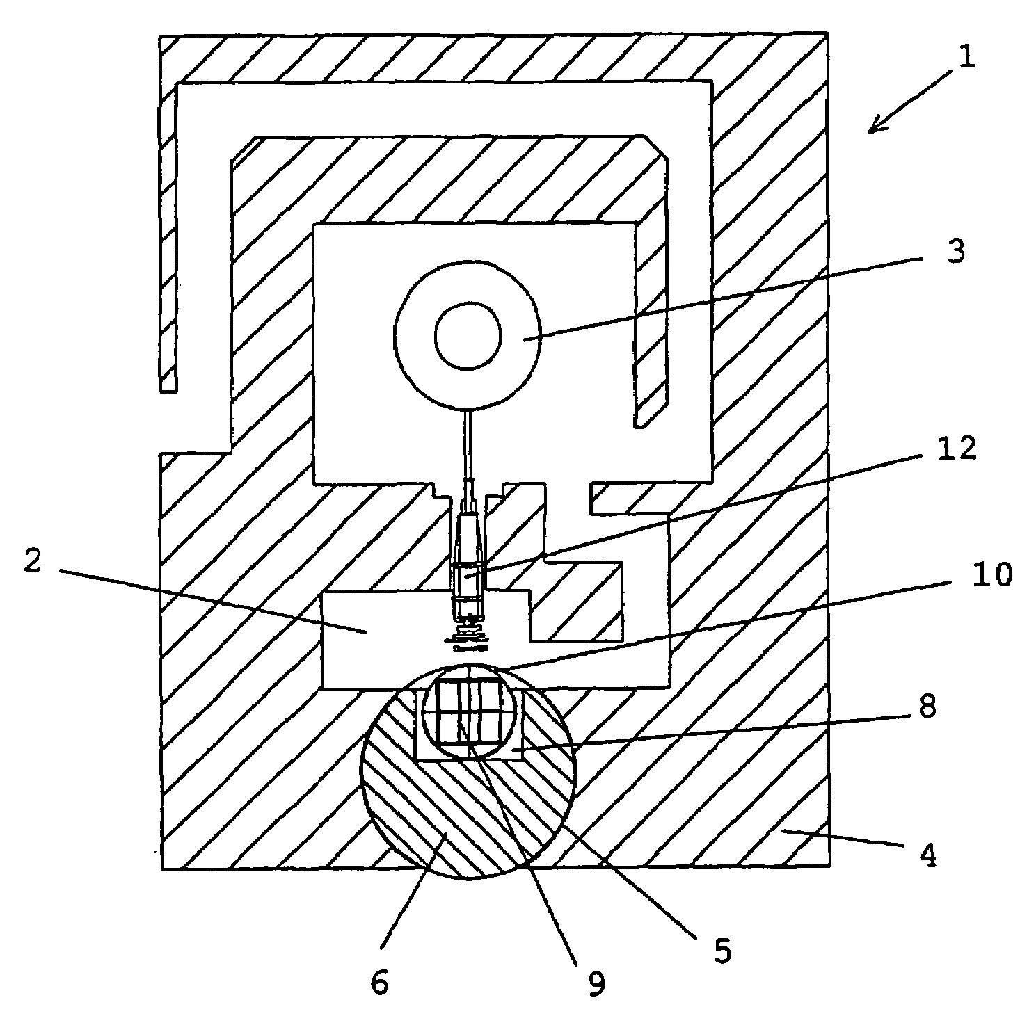
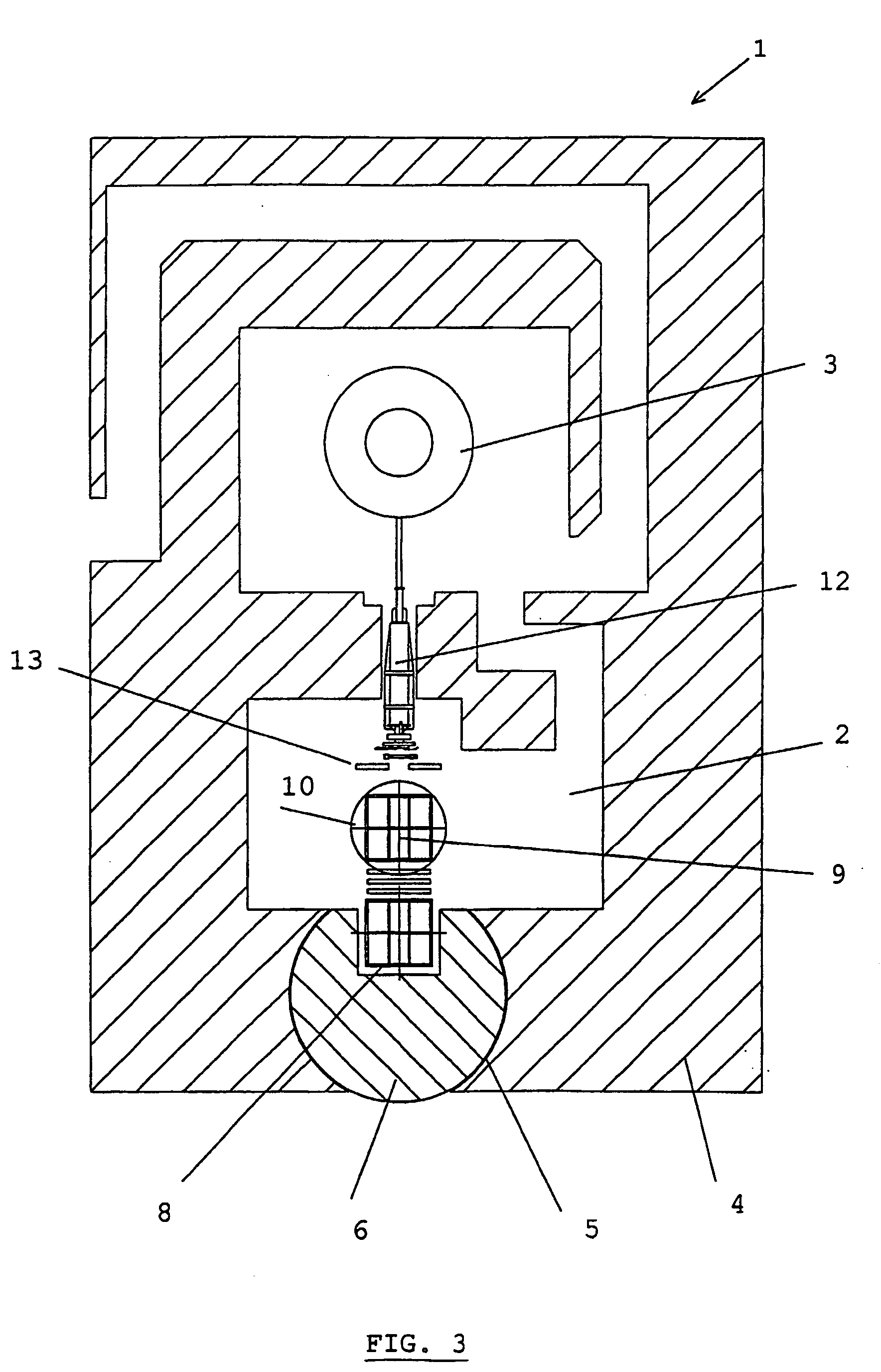
[0045]The apparatus 1 comprises an irradiation chamber 2 where irradiation takes place and a beam source 3 producing a beam of accelerated particles. The beam source may be a Rhodotron, as shown, a Dynamitron, or any type of charged particle accelerator. The irradiation chamber 2 and the beam source 3 are surrounded by a shielding wall 4. The shielding wall 4 may be made of concrete, or any radiation absorbing material such as iron, lead, or combinations thereof. The shielding wall 4 comprises a cylindrical opening 5. Fitted in said cylindrical opening 5, there is a cylindrical revolving door 6. This revolving door 6 rests on a ball bearing 7 and can be revolved around the cylinder axis by a motor (not shown). The revolving door is made of radiation shielding material. A recess 8 is made in the revolving door. The shape and size of said recess 8 is such that a product pallet or carrier 9 can ...


PUM

PropertyMeasurementUnit
thicknessesaaaaaaaaaa
energyaaaaaaaaaa
high-energy aaaaaaaaaa

Abstract

The present invention is related to an apparatus for irradiating products conveyed on a pallet, comprising a beam source (3) for producing a radiation beam, a shielding wall (4) encompassing an irradiation chamber (2) and a revolving cylindrical door (6) having a recess (8) for holding said pallet, for bringing said pallet in and out of the irradiation chamber (2) wherein said high-energy radiation beam is directed towards a lateral side of said revolving door (6), for irradiating said pallet in said recess (8), or brought before said recess (8).The present invention is also related to a process wherein a product pallet is brought into an irradiation chamber (2) through a revolving cylindrical door (6) having a recess (8), and irradiated while in said recess (8) or in front of said recess (8).

Description

FIELD OF THE INVENTION[0001]The present invention is related to an apparatus for irradiating products conveyed on pallets or carriers with a radiation beam.[0002]A possible application of such apparatus and process is the sterilisation of products and pasteurisation of food products.STATE OF THE ART[0003]Irradiation systems have widely been used for sterilising a great variety of products such as medical devices, food, food utensils or cosmetics by means of a high-energy ionising radiation source. Traditionally, the radiation source was a radioactive element producing gamma rays, such as Cobalt 60. For reasons of safety, i.a. in the disposal of waste, these systems are now replaced by systems relying on the use of an electron accelerator for producing a high-energy electron beam. This high-energy electron beam is either directed immediately to the product to be treated, or passed through a foil made of a high Z material, for producing X-rays.[0004]Typically, in these irradiation sys...

Claims


Application Information

Patent Timeline
Patent Type & Authority Patents(United States)
IPC IPC(8): G01N21/00A61L2/08E06B5/18G21F7/005G21K5/10
CPCA61L2/082A61L2/087G21F7/005G21K5/10A61L2202/24G21Y2002/202G21Y2002/301G21Y2002/304G21Y2004/30G21Y2004/40
Inventor BOL, JEAN-LOUISMULLIER, BENOITSTICHELBAUT, FREDERICNELSON, GLENN
Owner ION BEAM APPL
Learn More