
Method, system and apparatus for an enhanced electrically pumped oxygen iodine laser

an oxygen iodine laser and laser technology, applied in the direction of laser details, excitation process/apparatus, electrical apparatus, etc., can solve the problems of positive gain, all attempts to produce such a device have failed, etc., and achieve the effect of low ionization threshold and easy production

Active Publication Date: 2007-09-25
CU AEROSPACE +1
View PDF1 Cites 6 Cited by
  • Summary
  • Abstract
  • Description
  • Claims
  • Application Information

AI Technical Summary

Benefits of technology

These enhancements lead to the demonstration of positive gain and continuous wave laser operation, with increased O2(a) yields and improved laser output power, overcoming previous limitations in discharge stability and energy transfer efficiency.

Problems solved by technology

The basic idea of using an electric discharge to create singlet-delta oxygen to drive an energy transfer iodine laser dates back to 1974, but all attempts to produce such a device have failed for a variety of reasons (many related to an incomplete understanding of the complexity of the system as a whole).
Early attempts to implement electric discharges to generate O2(a) and transfer energy to iodine to make a laser failed to result in positive gain.

Method used


Image

  • Method, system and apparatus for an enhanced electrically pumped oxygen iodine laser
  • Method, system and apparatus for an enhanced electrically pumped oxygen iodine laser
  • Method, system and apparatus for an enhanced electrically pumped oxygen iodine laser

Examples


first embodiment

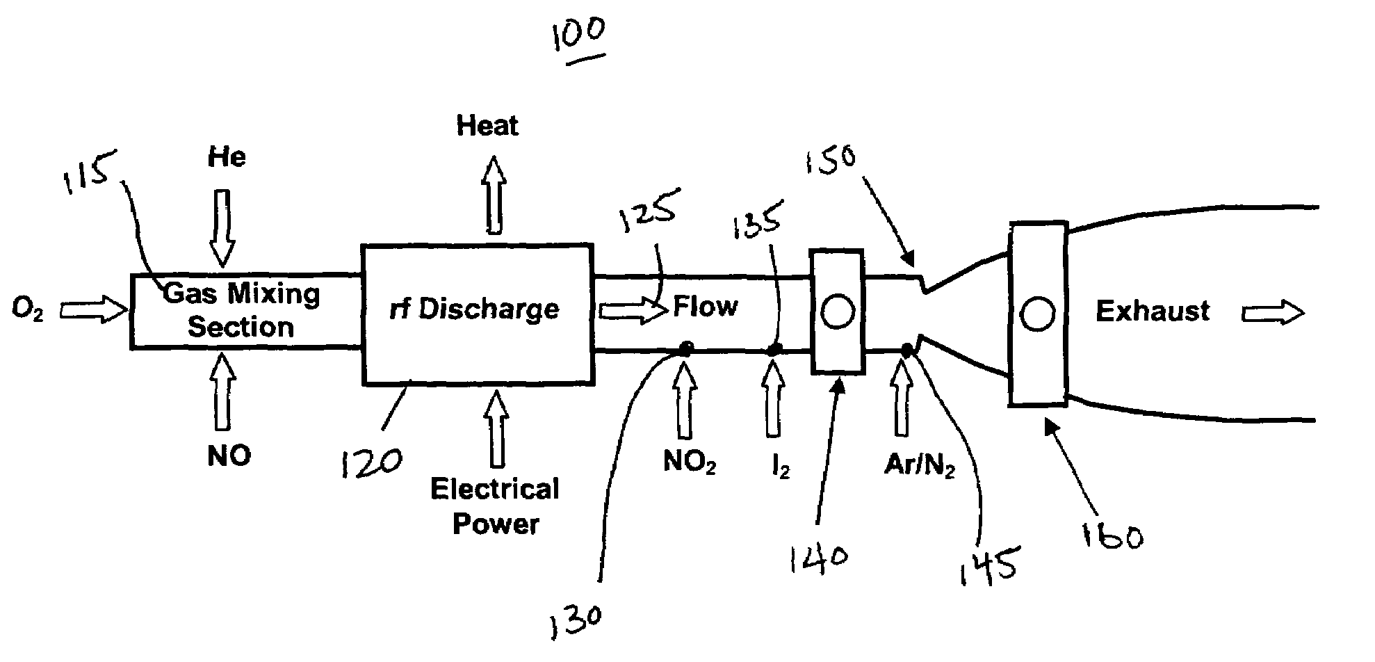
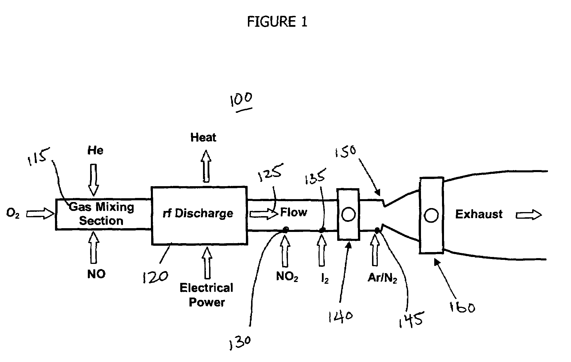
[0048]Referring now to FIG. 1 in a first embodiment an electrically pumped oxygen iodine laser (OIL) system is illustrated and generally referenced to as 100. The OIL system includes a first electrical generator 120 to produce a primary flow 125 containing singlet-delta oxygen O2(a1Δ). The first electrical generator 120 is a radio frequency (hereinafter rf) discharge generator between two internal hollow cathode electrodes (approximately 13 cm long) operating at about 13.56 MHz. The plasma zone is approximately 4.9 cm in diameter and 25 cm long, similar discharge configurations were a part of U.S. Pat. No. 6,501,780.

[0049]Two diagnostic ducts 140 and 160 were used for measurement purposes. The first diagnostic duct 140 was made in the subsonic region and has four windows through which simultaneous measurements are made of the optical emission from O2(a) at 1268 μm; O2(b1Σ) [also denoted O2(b) hereafter] at 762 nm; I* at 1315 μm; and the gain / absorption proportional to {[I*]−0.5·[I]}...

second embodiment

[0099]The first experiment of the run with 3.0 mmol / s of O2 mixed with 16.0 mmol / s of He and 0.15 mmol / s of NO flowing through the rf discharge. For the first experiment, a flow rate of 0.23 mmol / s NO2 was injected downstream and used to scavenge excess O atoms. The NO2 flow was accompanied by 2.0 mmol / s of carrier He diluent. The secondary stream consisted of ≈0.008 mmol / s of I2 with 2.0 mmol / s of secondary He diluent. The tertiary flow was 38 mmol / s of cold N2 gas at a temperature of ≈135 K. The pressures in the subsonic diagnostic duct and in the supersonic diagnostic cavity were 10.4 Torr and 1.35 Torr, respectively.

[0100]Gain for the above flow conditions at 450 W of rf discharge power is shown in FIG. 22 and peaks at 0.0067% cm−1 at line center. The laser resonator was subsequently installed around the supersonic flow cavity and simultaneous measurements of O2(a) yield and laser power were made using two 1 m concave mirrors with a reflectivity of ≈0.99986, mirrors #1 and #2 fr...


PUM


Abstract

In one embodiment of the present invention an oxygen iodine laser includes a gas mixing section. Ground state oxygen and a carrier gas are introduced into the first gas mixing section, sometimes separately. The laser includes a discharge region to generate at least said excited oxygen from the flow of the first gas mixing section. A sensitizer gas having a lower ionization threshold than ground state oxygen is also introduced into the first gas mixing section, such that electrons are more easily produced in the electrical generator. The laser system includes introducing a source of iodine into the excited singlet delta oxygen flow to generate a laser-active gas. In another embodiment a conditioner is placed into the gas mixing section to help mix the flow and / or introduce one or more of the aforementioned gases.

Description

CROSS REFERENCE TO RELATED APPLICATIONS[0001]This application claims benefit to U.S. Provisional Application 60 / 553,156 filed on Mar. 15, 2004.GOVERNMENT LICENSE[0002]The present invention was done under the following contracts with the Air Force Office of Scientific Research (AFOSR) under Contract #: F49620-02-1-0357 and the U.S. Army, Space and Missile Defense Command (USA / SMDC) under Contract #: DASG60-03-0098.FIELD OF THE INVENTION[0003]These technology enhancements significantly improve the discharge and post-discharge characteristics of an electrically pumped oxygen-iodine laser.BACKGROUND OF THE INVENTION[0004]The basic idea of using an electric discharge to create singlet-delta oxygen to drive an energy transfer iodine laser dates back to 1974, but all attempts to produce such a device have failed for a variety of reasons (many related to an incomplete understanding of the complexity of the system as a whole).[0005]Oxygen-iodine laser (OIL) systems operate on the electronic ...

Claims


Application Information

Patent Timeline
Patent Type & Authority Patents(United States)
IPC IPC(8): H01S3/095H01S3/09
CPCH01S3/223H01S3/0955H01S3/0979H01S3/134
Inventor CARROLL, DAVID LVERDEYEN, JOSEPH TSOLOMON, WAYNE CKING, DARREN M
Owner CU AEROSPACE
Learn More