
Pulse shaping which compensates for component distortion

a component distortion and pulse shaping technology, applied in the field of pulse shaping which compensates for component distortion, can solve problems such as non-linear distortion, and achieve the effects of extending the practical life, increasing power efficiency, and optimizing cost functions in qpsk modulation schemes

Inactive Publication Date: 2007-09-25
WSOU INVESTMENTS LLC
View PDF14 Cites 7 Cited by
  • Summary
  • Abstract
  • Description
  • Claims
  • Application Information

AI Technical Summary

Benefits of technology

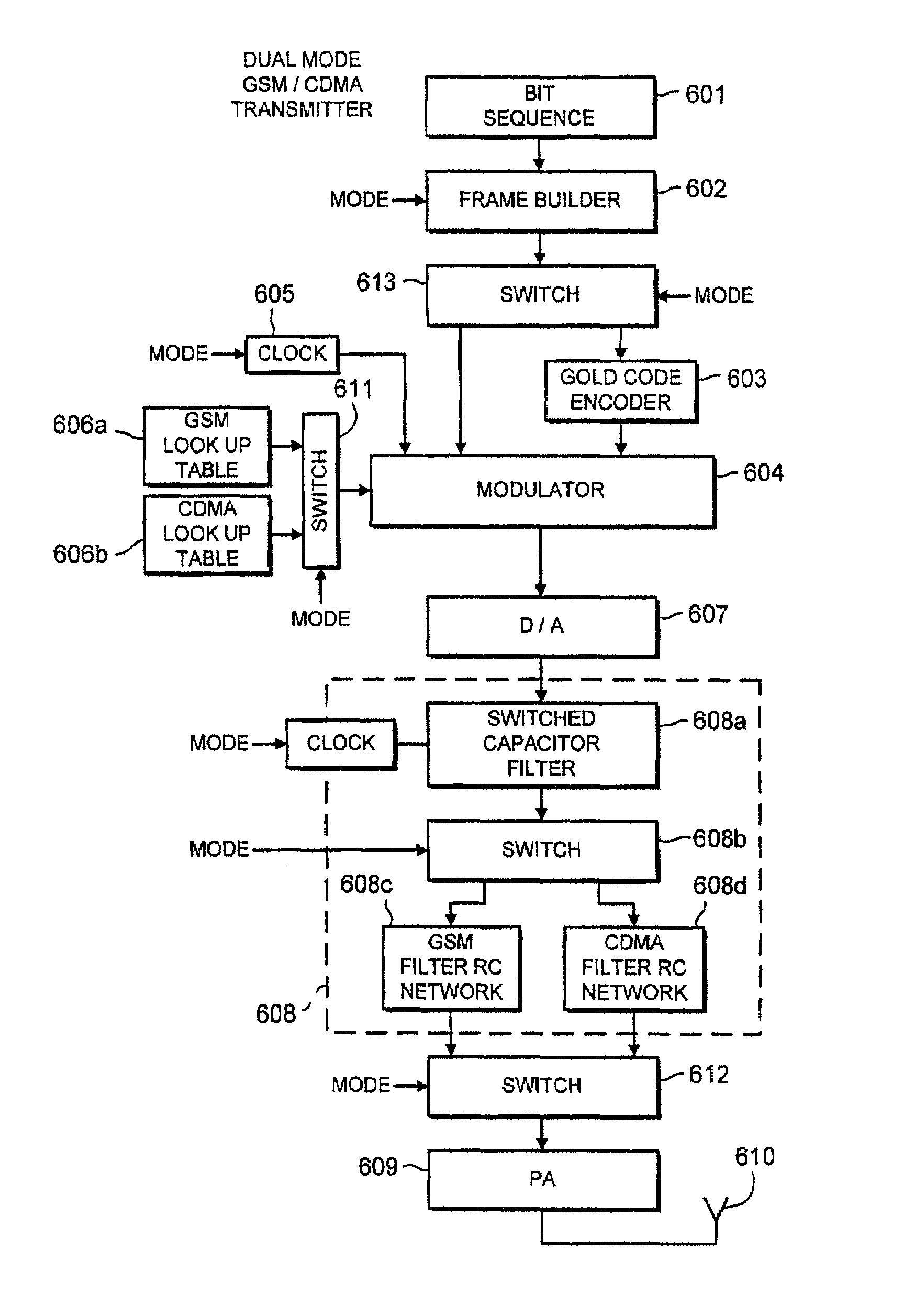
[0010]This method enables the designer to select from an expanded choice of components for use in the transmitter. For example, it may enable a designer to use a more efficient power amplifier, because the method provides pre-distortion to compensate for any variation in efficiency. Also, this same distortion can be used for each transmitter designed, and thus eliminates the need for testing and modifying individual devices during manufacture. Furthermore, once the defined pulse function has been implemented in a transmitter there is no need for further pre-distortion compensation. That is, there is no active pre-distortion—this method provides a single step static pre-distortion.
[0058]As well as using MSK modulation in a CDMA system, pulse shaping would allow the cost functions in a QPSK modulation scheme to be optimized. This would allow the power efficiency to increase with perhaps some resulting increase in the BER and decrease in spectral efficiency. The freedom to select a pulse shape unconstrained by conventional root raised cosines and gaussian pulses allows the cost function in any of these modulation schemes to be optimized to meet desired parameters. This provides greater freedom in designing a third generation or enhanced second generation system, having desired parameters that are considered as set of weighted costs in an optimization calculation.

Problems solved by technology

Non-linear distortion may result by virtue of the component itself being non-linear.

Method used


Image

  • Pulse shaping which compensates for component distortion
  • Pulse shaping which compensates for component distortion
  • Pulse shaping which compensates for component distortion

Examples


Embodiment Construction

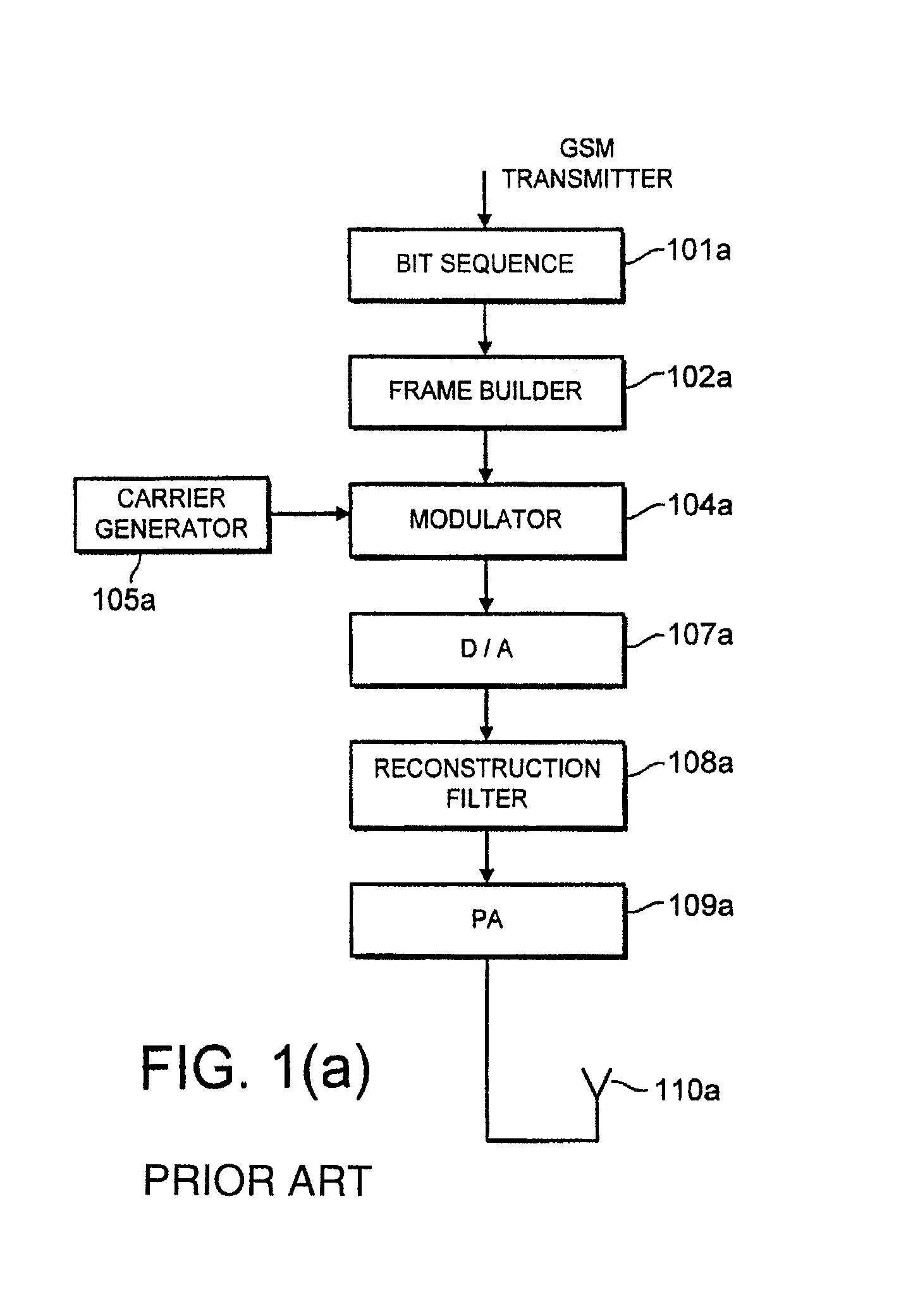
[0078]FIG. 1a illustrates a GSM transmitter. GSM conventionally comprises a frame structure as shown in FIG. 1c. A bit sequence 101a to be transmitted is input to a frame builder 102a of the transmitter, which puts the bits in the appropriate portion of a burst within a time slot of a TDMA frame. The bit stream is then forwarded to a modulator 104a. Conventionally this modulator would be a GMSK modulator, and thus the signal would be put through a Gaussian filter. A clock or carrier generator 105a provides the carrier signal. The modulated signal is input to a digital analogue converter 107a. This analogue signal is then reconstructed by reconstruction filter 108a. This filter might typically comprise a switch capacitor filter for performing some of the spectral shaping and an analogue filter, such as an RC filter, for mainly dealing with residual shaping. Finally, the signal is amplified by a power amplifier 109a and is transmitted via antenna 110a.

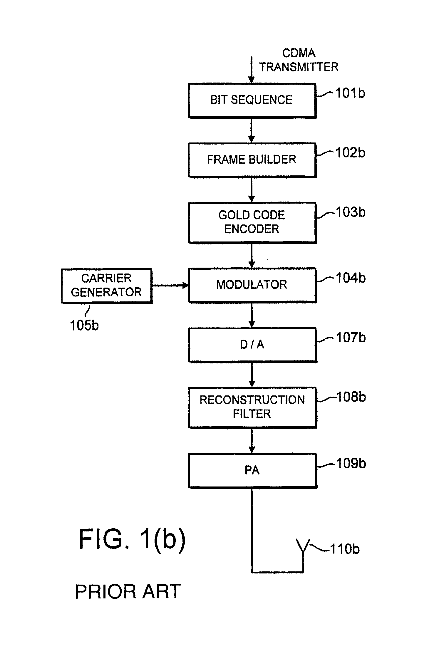
[0079]FIG. 1(b) illustrates a co...


PUM


Abstract

A method is provided for defining a pulse function shape for acting on a data stream for transmission in a telecommunication system which compensates for distortion by a component of the transmitter. The method comprises defining desired cost parameters (e.g., error functions for amplitude, BER, bandwidth, energy, AFC) and defining the shape of the pulse function in dependence of the desired cost parameters and the distortion to be compensated for. A pulse generator, modulator and communications device providing such a pulse function are also provided. Application in dual mode TDMA / CDMA system.

Description

CROSS REFERENCE TO RELATED APPLICATION[0001]This application is a continuation of PCT application PCT / GB99 / 00201, filed Jan. 21, 1999.BACKGROUND OF THE INVENTION[0002]The present invention relates to a communication device which is provided with pre-distortion to compensate for distortion introduced by components in the device, and a method of such pre-distortion.[0003]In particular, the present invention relates to the compensation of distortion by components in a transmitter.[0004]Components in the transmitter cause an information signal to be distorted prior to transmission to differing degrees. Two major factors affect this distortion, namely ramp up and ramp down, and component tolerances. Whilst individually such distortions may not affect the signal to be transmitted significantly, there is a possibility that the superposition of such signals is unacceptable as it is outside the limits defined by the appropriate telecommunication standard. For example, such distortion may cau...

Claims


Application Information

Patent Timeline
IPC IPC(8): H04L27/00H04B1/707H03F1/32H04B7/26H04J13/00H04L25/03H04L27/12H04L27/20H04L27/36
CPCH03F3/24H03F1/32H03F2200/451H04L27/2017H04L27/18H04L27/20H04L27/366H04L27/368H04B1/0475H04L25/0384H04L27/10
Inventor LOBO, NATIVIDADEL
Owner WSOU INVESTMENTS LLC
Learn More