Dual-use radial turbomachine

a turbomachine and dual-use technology, applied in the direction of machines/engines, stators, liquid fuel engines, etc., can solve the problems of large waste of energy that might otherwise be used, relatively high pressure and high temperature of turbomachine in such systems, and high cost in their manufacture and use, so as to achieve the effect of effective use of waste hea

Active Publication Date: 2007-10-16
RTX CORP
View PDF48 Cites 48 Cited by
  • Summary
  • Abstract
  • Description
  • Claims
  • Application Information

AI Technical Summary

Benefits of technology

[0015]Briefly, in accordance with one aspect of the invention, a centrifugal compressor which is designed for compression of refrigerant for purposes of air conditioning, is used in a reverse flow relationship so as to thereby operate as a turbine in a closed organic rankine cycle system. In this way, an existing hardware system which is relatively inexpensive, is used to effectively meet the requirements of an organic rankine cycle turbine for the effective use of waste heat.
[0016]By another aspect of the invention, a centrifugal compressor having a vaned diffuser is effectively used as a power generating turbine with flow directing nozzles when used in a reverse flow arrangement.

Problems solved by technology

The turbines in such systems are designed to operate at relatively high pressures and high temperatures and are relatively expensive in their manufacture and use.
With the advent of the energy crisis and, the need to conserve, and to more effectively use, our available energies, rankine cycle systems have been used to capture the so called “waste heat”, that was otherwise being lost to the atmosphere and, as such, was indirectly detrimental to the environment by requiring more fuel for power production than necessary.
While the combustion products of methane (CO2 and H2O) do less harm to the environment, it is a great waste of energy that might otherwise be used.
With the use of either diesel engines or microturbines, it is necessary to first clean the methane gas by filtering or the like, and with diesel engines, there is necessarily significant maintenance involved.
Further, with either of these approaches there is still a great deal of energy that is passed to the atmosphere by way of the exhaust gases.
This requirement is further complicated by the fact that the design of the components may necessarily change with different applications.
For example, inasmuch as various sources of waste heat are necessarily at substantially different temperatures, a single design of a rankine cycle system for use with all such sources will not necessarily ensure the effective and economical use of those waste heat sources.

Method used


Image

  • Dual-use radial turbomachine
  • Dual-use radial turbomachine
  • Dual-use radial turbomachine

Examples


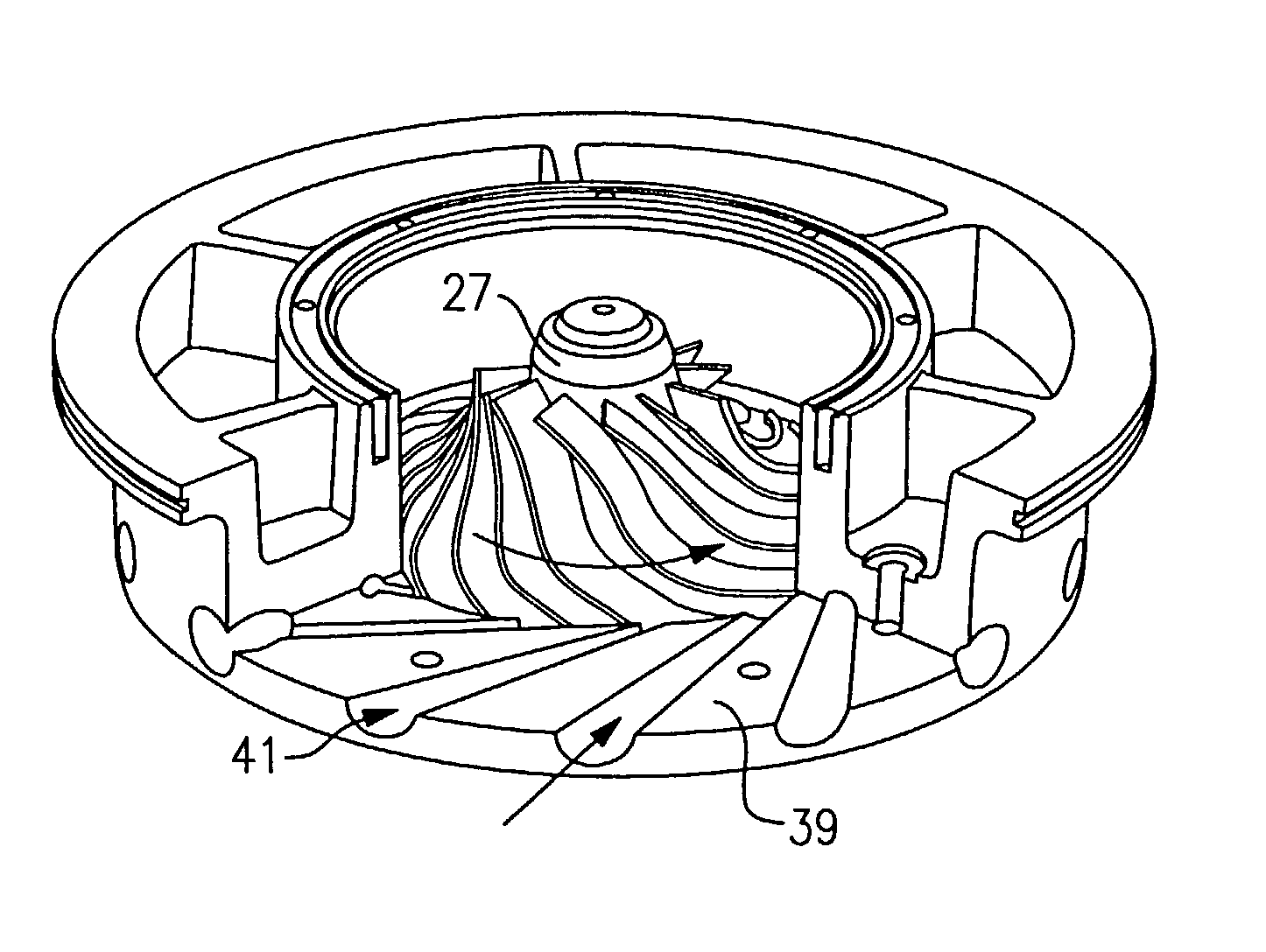
Embodiment Construction

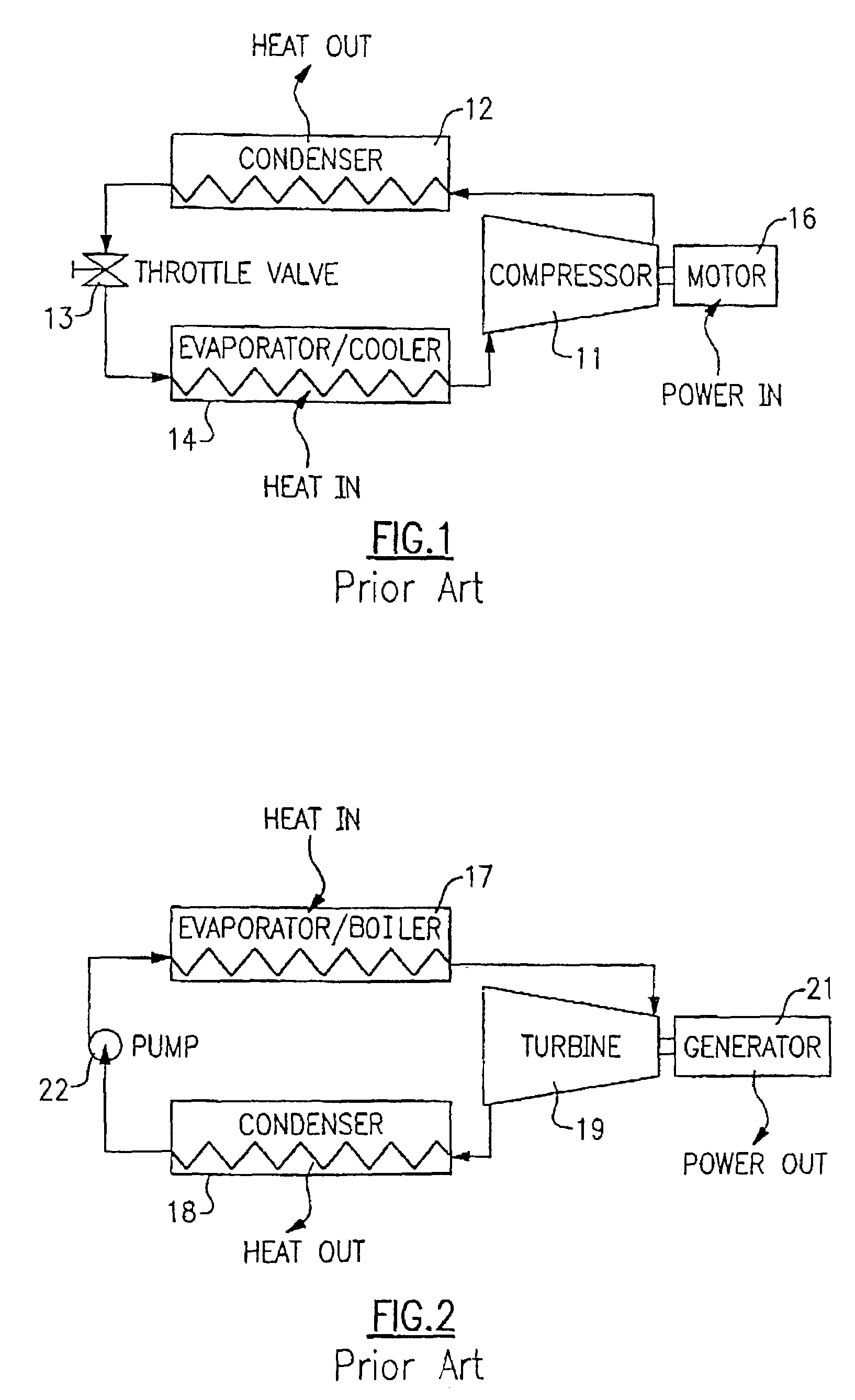
[0033]Referring now to FIG. 1, a typical vapor compression cycle is shown as comprising, in serial flow relationship, a compressor 11, a condenser 12, a throttle valve 13, and an evaporator / cooler 14. Within this cycle a refrigerant, such as R-11, R-22, or R-134a is caused to flow through the system in a counterclockwise direction as indicated by the arrows.

[0034]The compressor 11 which is driven by a motor 16 receives refrigerant vapor from the evaporator / cooler 14 and compresses it to a higher temperature and pressure, with the relatively hot vapor then passing to the condenser 12 where it is cooled and condensed to a liquid state by a heat exchange relationship with a cooling medium such as air or water. The liquid refrigerant then passes from the condenser to a throttle valve wherein the refrigerant is expanded to a low temperature two-phase liquid / vapor state as it passes to the evaporator / cooler 14. The evaporator liquid provides a cooling effect to air or water passing throug...


PUM


Abstract

The impeller is preferably modified to use back swept, radial or forward swept blades to accommodate relatively low, medium and high lift, respectively applications for both centrifugal compressor and turbine rotor use.

Description

BACKGROUND OF THE INVENTION[0001]This invention relates generally to organic rankine cycle systems and, more particularly, to an economical and practical method and apparatus therefor.[0002]The well known closed rankine cycle comprises a boiler or evaporator for the evaporation of a motive fluid, a turbine fed with vapor from the boiler to drive the generator or other load, a condenser for condensing the exhaust vapors from the turbine and a means, such as a pump, for recycling the condensed fluid to the boiler. Such a system as is shown and described in U.S. Pat. No. 3,393,515.[0003]Such rankine cycle systems are commonly used for the purpose of generating electrical power that is provided to a power distribution system, or grid, for residential and commercial use across the country. The motive fluid used in such systems is often water, with the turbine then being driven by steam. The source of heat to the boiler can be of any form of fossil fuel e.g. oil, coal, natural gas or nucl...

Claims


Application Information

Patent Timeline
Patent Type & Authority Patents(United States)
IPC IPC(8): F02G3/00F01D5/04F01K25/08F04D25/06F04D29/44
CPCF01D5/048F04D29/444F04D25/06F01K25/08F05D2250/52F01D5/02F01D5/04F01K25/00
Inventor BRASZ, JOOST J.
Owner RTX CORP
Why Eureka
Try Eureka