Active search sensor and a method of detection using non-specular reflections

a technology of active search sensor and non-speculative reflection, which is applied in the field of active laser search system, can solve the problems of large number of laser sweeps that cannot detect targets, system problems, and at best problems such as retroreflection search, and achieve the effect of avoiding the detection of target objects by large number of laser sweeps

Active Publication Date: 2007-10-16
BAE SYST INFORMATION & ELECTRONICS SYST INTEGRATION INC
View PDF5 Cites 45 Cited by
  • Summary
  • Abstract
  • Description
  • Claims
  • Application Information

AI Technical Summary

Benefits of technology

[0021]It is a further finding of this invention that this scatter, when focused out of the system, can be detected. However, because of the low intensity of non-specular returns one must be able to discriminate against scattering or clutter from the ground. It will be appreciated that sand, dirt, pavement, foliage and other earth-bound objects will to some extent also scatter the incoming laser radiation. It is against such clutter that any threat sensor competes for detection.
[0025]A key enabler to this method is direct access to row and column registers that signal detection of an event on any pixel, thereby eliminating the overhead functions associated with having to read all the pixels in a two dimensional array. Instead of reading all the pixels, the entire frame content is determined by which registers have signaled an event. All other pixels have a logical zero. Each detector thus has a one bit analog-to-digital converter.
[0029]In short, by using a direct-reading, thresholded focal plane array for the detector in an active search system, and by setting the threshold at a level that ignores temporally spread clutter, one can detect an event, meaning the detection of a target, by declaring an event when the threshold has been exceeded. Moreover, the detection of a target employing any kind of optical system may be reliably obtained with dramatically fewer sweeps of the search system.
[0032]In summary, it has been found that target optics produce non-specular augmented optical returns when interrogated by a laser pulse. This non-specular returned radiation is detected by an active laser search system employing a direct-reading, thresholded focal plane detector to be able to detect non-cooperating targets having optics that employ a focal plane. This is accomplished by setting the threshold for the detector array to discriminate against the smeared-out returns from ground clutter, while at the same time responding only to the relatively short non-specular returns from the target's optical system. The pulses returned from target optics have a pulse width commensurate with the pulse width of the transmitted pulse. The subject system thus discriminates against ground clutter while at the same time reducing the number of sweeps to guarantee detection of a target within the search area swept by the interrogating laser.

Problems solved by technology

Thus, looking for retroreflections is at best problematical.
What makes such a system more problematical is the fact that most optical designers tilt the focal plane associated with the optical system with respect to the optical axis or boresight of the system.
Thus even a large number of laser sweeps can fail to detect a target of interest if such angled focal planes are employed.
As mentioned above, the Wild et al. system, which relies upon retroreflection, also suffers from the problem that the optical axis of the target optic usually is not pointed in the direction of the interrogating laser.
Thus, when using an active search system to scan a given area on the ground, the probability of detecting such a specular reflection is exceedingly low due to the small amount of time that the target optics are pointed at the interrogating laser.
More particularly, there are several factors that may have prevented the widespread use of the techniques discovered by Wild et al. in active search applications.
Thus when using an active search system to scan a given patch of ground, the detection probability is low indeed due to the small amount of time that the target optics and interrogating laser are mutually co-aligned.
Clear air turbulence, for example, further exacerbates the intermittent return problem.
Finally, ground clutter is a problem and is a consequence of the preceding effects.
These circumstances have led to the failure of previous active search systems intended to find passive tracking sensors.
Furthermore, they have limited systems in development to using passive means such as missile launch detection to perform the initial acquisition.

Method used


Image

  • Active search sensor and a method of detection using non-specular reflections
  • Active search sensor and a method of detection using non-specular reflections
  • Active search sensor and a method of detection using non-specular reflections

Examples


Embodiment Construction

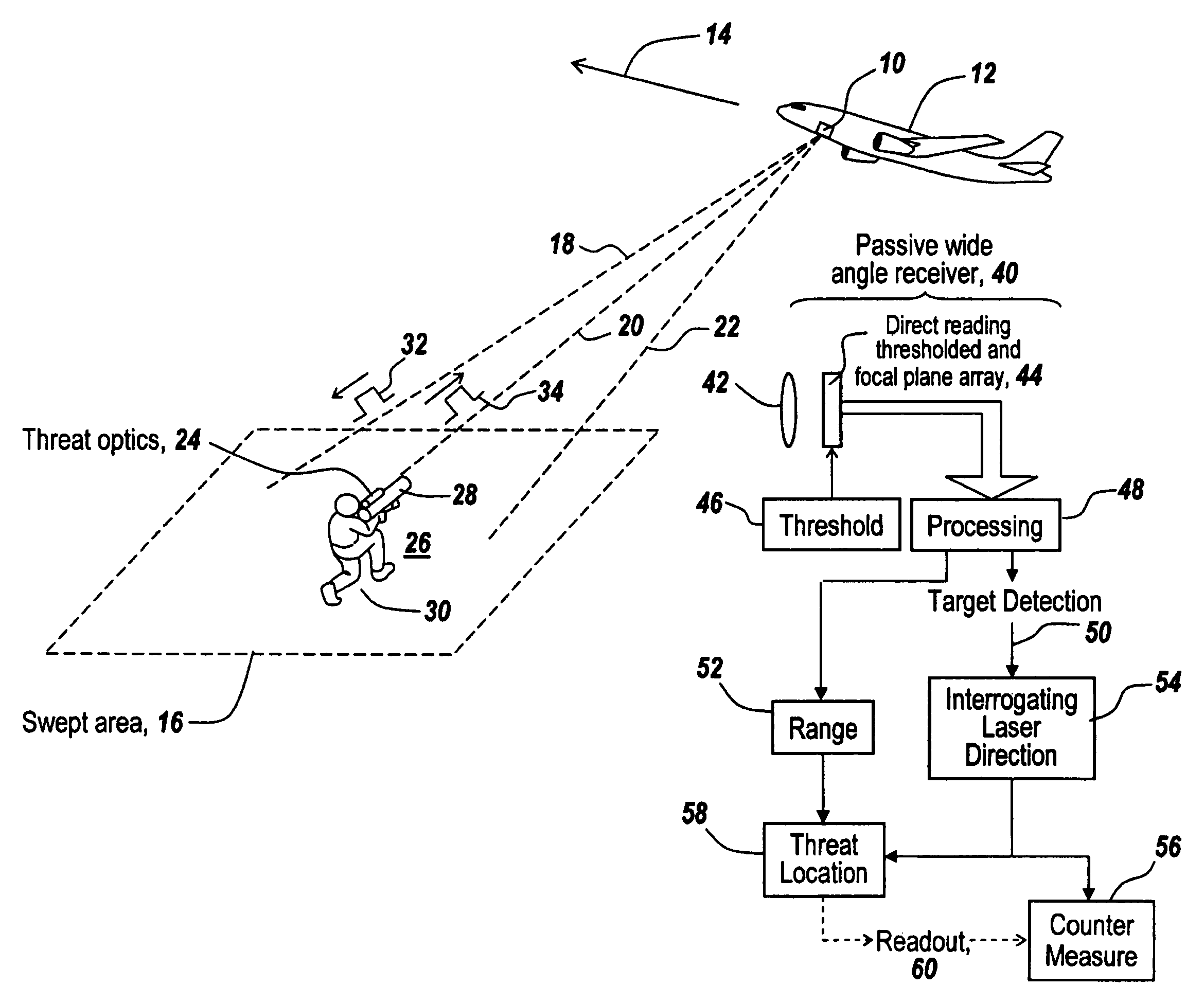
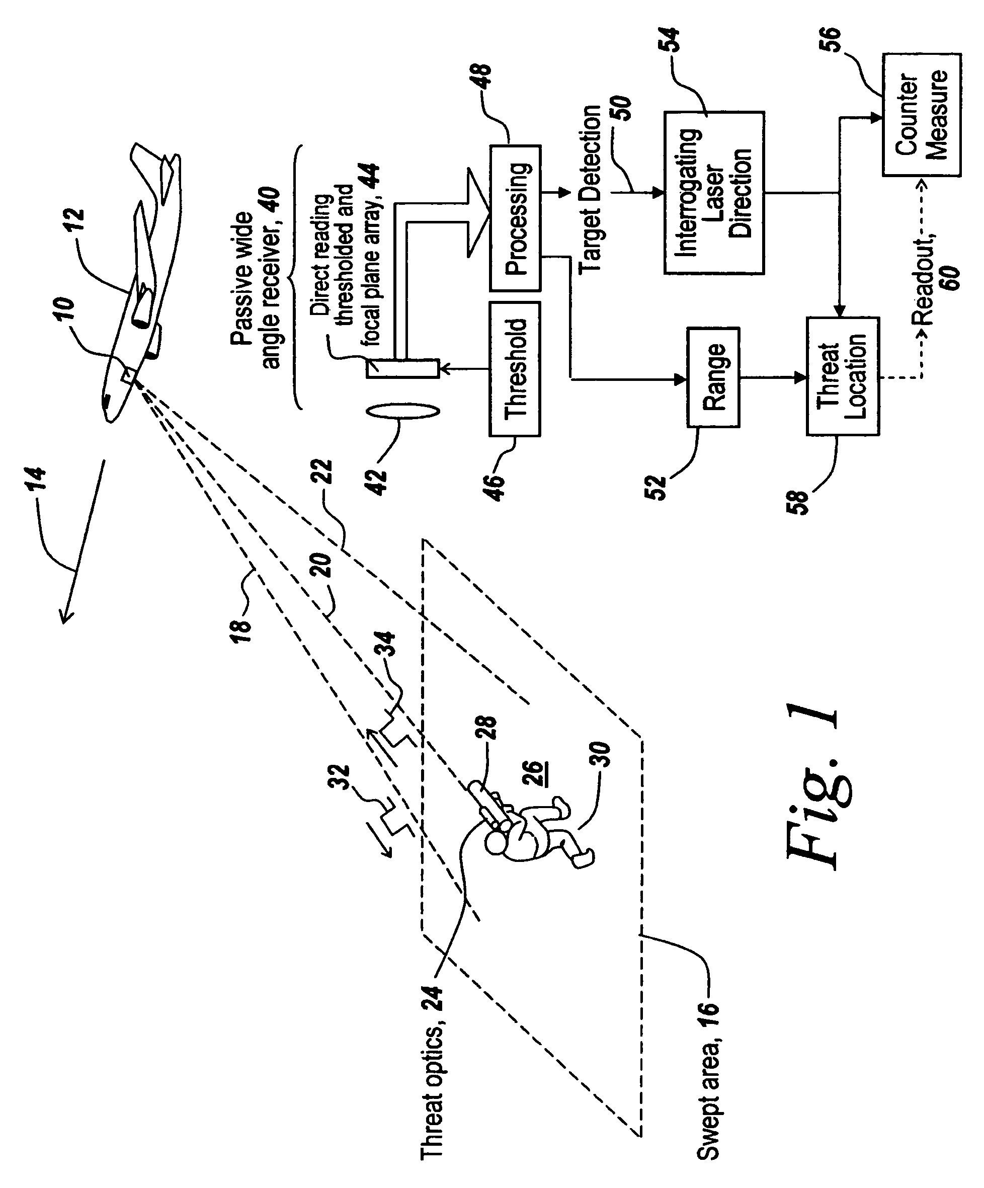
[0045]Referring now to FIG. 1, an aircraft 12 flying in the direction indicated by arrow 14 and possessing an active search system 10 is shown. In this active system narrow laser pulses are projected in a scanned pattern along the directions 18, 20 and 22 over an area 16 to be searched. Here the narrow laser pulses that illuminate area 16 are denoted by reference character 32. It is the purpose of these scanned laser pulses to sweep area 16 in a reasonable time so that one can detect the presence of the optics 24 that accompany a threat ordnance 28 located at 26.

[0046]The threat is considered to have threat optics if, for instance, a lens is involved and there is something behind the lens at its focal plane. This could be, night vision goggles worn by an individual 30, or it could be any kind of telescopic sight used for aiming and or firing ordnance 28 at aircraft 12.

[0047]It is the purpose of system 10 to project a narrow pulse 32 towards area 16 and to detect return pulses 34 tha...


PUM

PropertyMeasurementUnit
lengthaaaaaaaaaa
lengthaaaaaaaaaa
pulse widthaaaaaaaaaa

Abstract

It has been found that target optics produce non-specular, augmented optical returns when interrogated by a laser pulse. This non-specular radiation is detected by an active laser search system employing a direct-reading, thresholded focal plane detector that is able to detect non-cooperating targets with optics that employ a detector or optical element at the focal plane of their receiving optics. The pulses returned from such target optics have a width commensurate with the original transmitted pulse width, whereas passive background noise and the spread out active returns from the ground exhibit temporally long returns. By setting the sensor threshold sufficiently high, the system discriminates against noise and clutter while at the same time reducing the number of sweeps required to detect a target within the search area.

Description

RELATED APPLICATIONS[0001]This Application claims rights under 35 U.S.C. 119(e) from U.S. application Ser. No. 60 / 547,990 filed Feb. 26, 2004, the contents of which are incorporated herein by reference.FIELD OF THE INVENTION[0002]This invention relates to active laser search systems and more particularly to the use of an improved active sensor receiver detector array that can detect non-specular reflections from illuminated optical systems.BACKGROUND OF THE INVENTION[0003]As described in U.S. Pat. No. 6,603,134 issued to Norman R. Wild and Paul M. Leavey, Jr. on Aug. 5, 2003, assigned to the assignee hereof and incorporated herein by reference, a system for detecting target threats is described in which a high-energy laser is scanned across an area on the ground and retroreflections from the human eye or the focal plane associated with an optical system are detected, thus to give an indication of the presence of the target within the scanned field.[0004]As described in the Wild pate...

Claims


Application Information

Patent Timeline
Patent Type & Authority Patents(United States)
IPC IPC(8): G02F1/01G01C21/02G01C3/00G01C3/08G01J1/18G01S7/48G01S7/495G01S17/42
CPCG01S17/42G01S7/495G01S7/4802G01J1/18
Inventor WEBER, JONATHAN L.O'DONNELL, TIMOTHY J.MARLER, NORMAN O.LANIER, KATHRYN G.
Owner BAE SYST INFORMATION & ELECTRONICS SYST INTEGRATION INC
Why Eureka
Try Eureka