Signal detection circuit capable of automatically adjusting threshold value

a detection circuit and threshold value technology, applied in the direction of pulse technique, pulse circuit, multi-input and output pulses, etc., can solve problems such as failure to detect input signals, and achieve the effect of suppressing variation in detection results

Inactive Publication Date: 2007-10-16
COLLABO INNOVATIONS INC
View PDF10 Cites 19 Cited by
  • Summary
  • Abstract
  • Description
  • Claims
  • Application Information

AI Technical Summary

Benefits of technology

[0011]An object of the present invention is avoiding a variation in detection result among signal detection circuits.
[0014]The present invention suppresses a variation in detection result among signal detection circuits, and thus is useful for a signal detection circuit, such as a squelch circuit for detecting presence / absence of a reception signal, particularly in the case of handling a small-amplitude input signal and requiring high-speed response.

Problems solved by technology

On the contrary, if the threshold voltage is set excessively high, high-frequency components of the input signals DRX and NDRX will fail to be detected, resulting in failure in detection of an input signal although the input signals DRX and NDRX are input, as shown in FIG. 9B.
Therefore, a given threshold value, if set for signal detection circuits, is not necessarily appropriate, and the detection result may vary among the signal detection circuits.

Method used


Image

  • Signal detection circuit capable of automatically adjusting threshold value
  • Signal detection circuit capable of automatically adjusting threshold value
  • Signal detection circuit capable of automatically adjusting threshold value

Examples


first embodiment

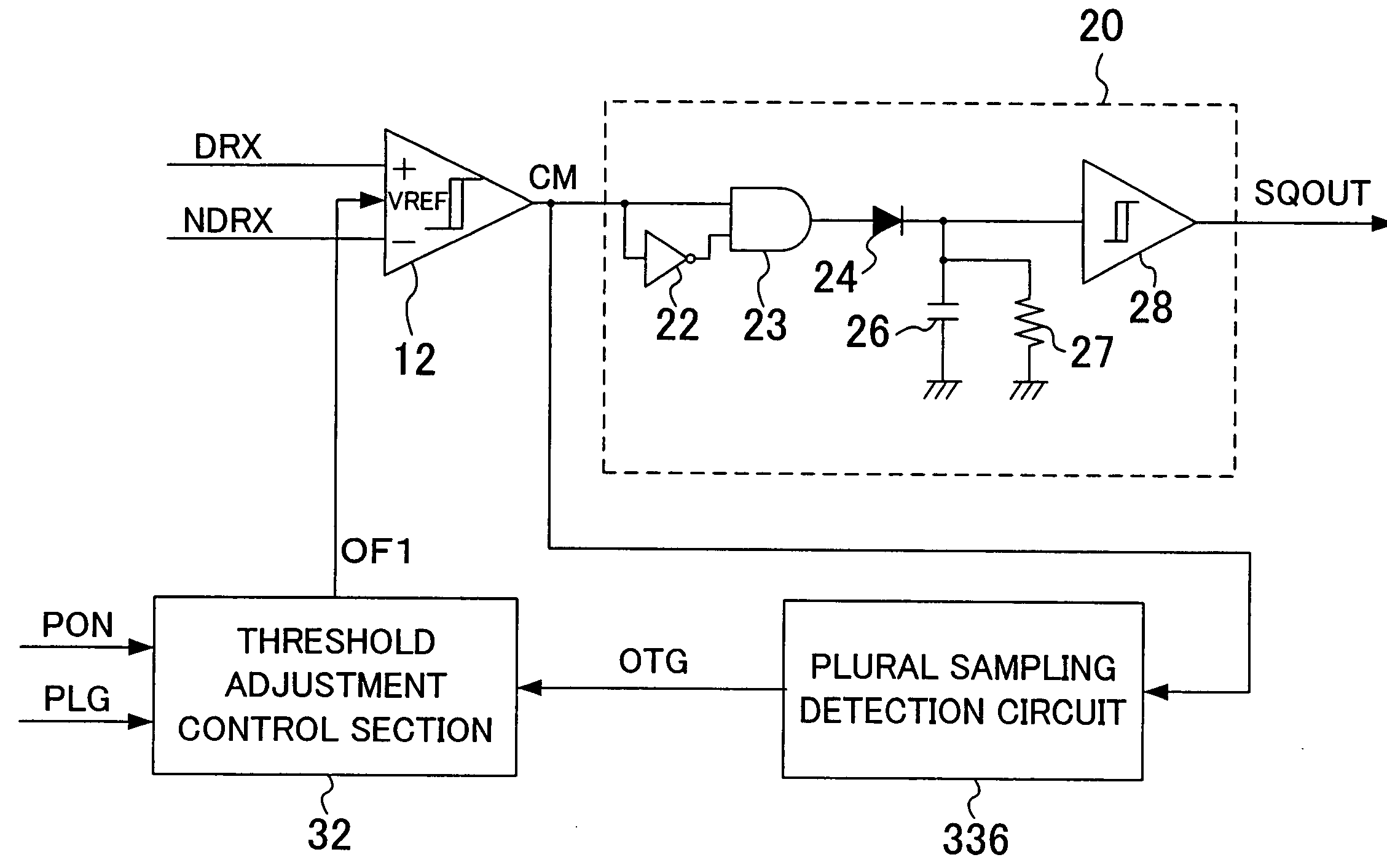
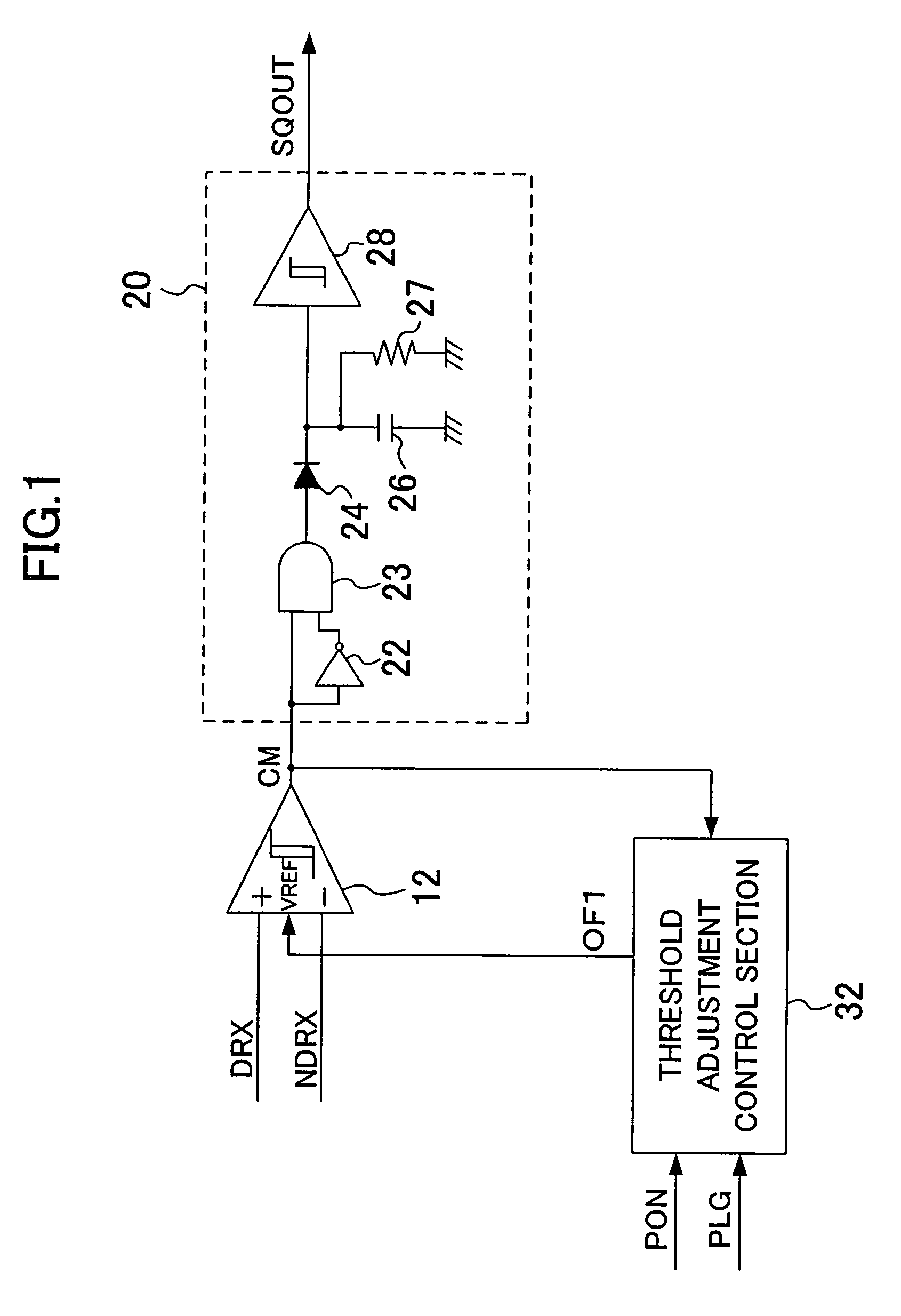
[0025]FIG. 1 is a block diagram of a signal detection circuit of the first embodiment of the present invention. The signal detection circuit of FIG. 1 includes a comparator 12 as the comparison section, a detection section 20 and a threshold adjustment control section 32. The detection section 20 includes an inverter 22, an AND gate 23, a diode 24, a capacitor 26, a resistance 27 and a buffer 28.

[0026]Two input signals DRX and NDRX constitute a differential signal. The input signal DRX is input into a positive input terminal + of the comparator 12, the input signal NDRX into a negative input terminal − thereof, and a detection level adjustment signal OF1 into a reference input terminal VREF thereof.

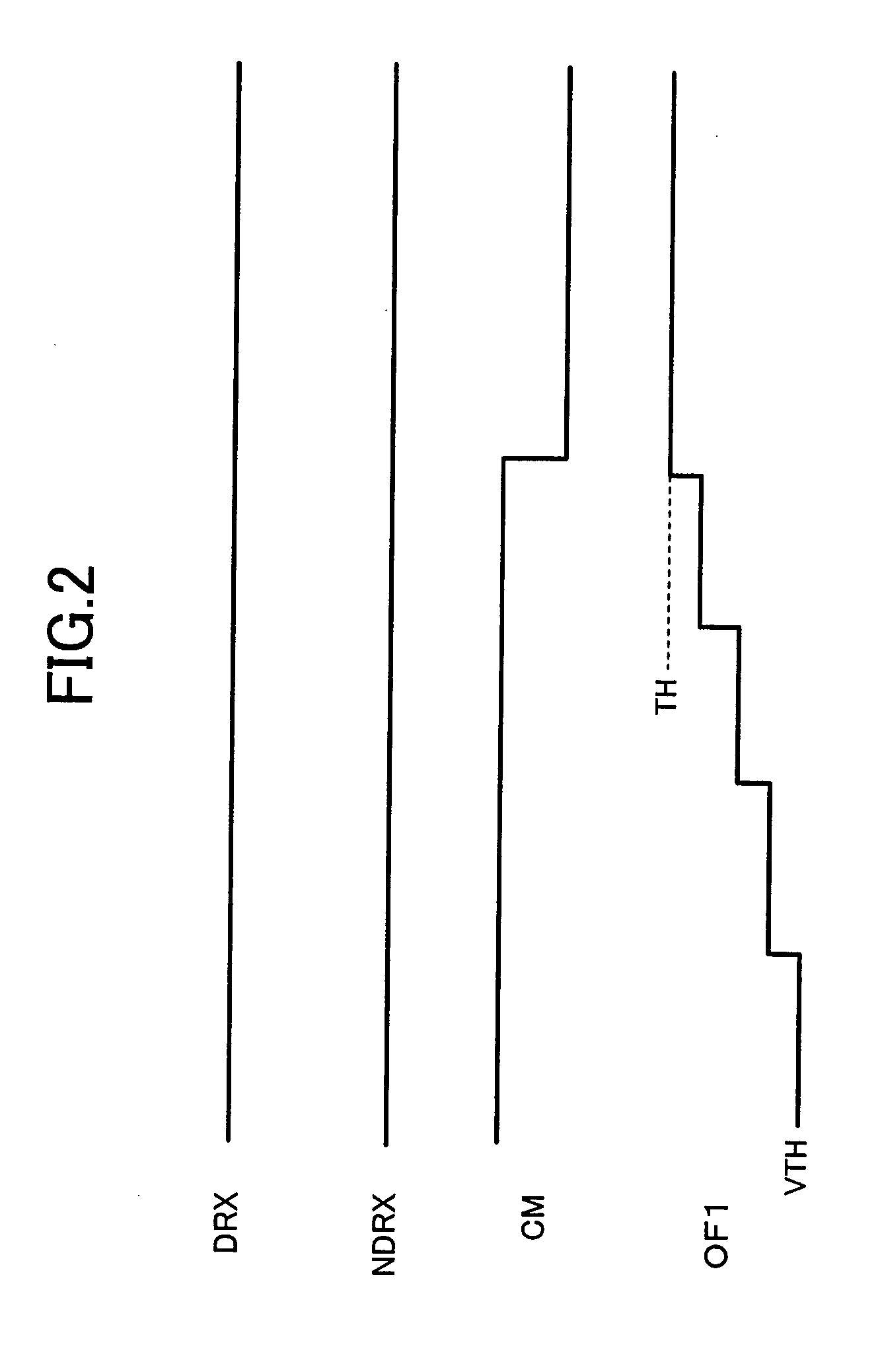
[0027]The comparator 12 sets its threshold voltage in response to the detection level adjustment signal OF1. Assume herein that the comparator 12 sets a higher threshold voltage as the potential of the detection level adjustment signal OF1 is higher.

[0028]The comparator 12, which exhibits...

second embodiment

[0059]FIG 7 is a block diagram of a signal detection circuit of the second embodiment of the present invention. The signal detection circuit of FIG. 7 includes a comparison section 410, the detection section 20 and a threshold adjustment control section 432. The comparison section 410 includes comparators 411 and 412, an OR gate 413 and voltage generators 416 and 417. The detection section 20 is the same as that described above with reference to FIG. 1 and therefore description thereof is omitted here.

[0060]The threshold adjustment control section 432 generates detection level adjustment signals OF1 and OF2 in response to the detection signal CM and outputs the signals to the voltage generators 416 and 417, respectively. The voltage generator416 generates a signal corresponding to the detection level adjustment signal OF1 and outputs the resultant signal to a reference input terminal of the comparator 411. The voltage generator 417 generates a signal corresponding to the detection l...


PUM


Abstract

The signal detection circuit of the present invention includes: a comparison section for comparing the absolute value of a voltage of an input differential signal with a threshold voltage corresponding to a first detection level adjustment signal to detect presence / absence of an input signal and outputting a detection signal indicating the detection result; a threshold adjustment control section for generating the first detection level adjustment signal in response to the detection signal and outputting the generated signal; and a detection section for detecting whether or not the level of the detection signal changes repeatedly. During the time of no input of the differential signal, the threshold adjustment control section changes the first detection level adjustment signal so that the threshold voltage monotonically increases or decreases until the detection signal is inverted, to determine the first detection level adjustment signal that makes the threshold voltage appropriate, and outputs the determined signal.

Description

BACKGROUND OF THE INVENTION[0001]The present invention relates to a device for receiving digital data, and more particularly, to a signal detection circuit for detecting presence / absence of a reception signal.[0002]In serial communications, a signal detection circuit for detecting whether or not a prescribed signal is being input is often used. Such a signal detection circuit determines that an input signal is valid if the absolute value of the voltage of the input signal is equal to or more than a predetermined value and is not valid if the absolute value is less than the predetermined value. In Universal Serial Bus (USB) and Serial AT Attachment (serial ATA), the signal detection circuit is used for a return sequence from an initialize sequence and a power management state. In particular, in Serial ATA, the signal detection circuit is used for detecting an out-of-band (OOB) signal, in addition to detecting the signal state during communications.[0003]The OOB signal is a signal hav...

Claims


Application Information

Patent Timeline
Patent Type & Authority Patents(United States)
IPC IPC(8): H03K5/22
CPCH03K5/19
Inventor HATOOKA, KAZUYAYOSHIZAKI, SHOICHIIMAMURA, KOKI
Owner COLLABO INNOVATIONS INC
Why Eureka
Try Eureka