Optical transmission network with asynchronous mapping and demapping and digital wrapper frame for the same

a technology of optical transmission network and asynchronous mapping, applied in data switching network, frequency-division multiplex, instruments, etc., can solve the problems of adding system costs (cogs), and achieve the effect of reducing the overall cost of manufacture, high cost, and high cos

Active Publication Date: 2007-10-23
INFINERA CORP
View PDF10 Cites 45 Cited by
  • Summary
  • Abstract
  • Description
  • Claims
  • Application Information

AI Technical Summary

Benefits of technology

[0015]The optical transmission network of this invention is inherently asynchronous due to the utilization of a variable overhead ratio (V-OHR). The network architecture makes extensive use of OEO regeneration, i.e., deals with any electronic reconditioning to correct for transmission impairments, such as, for example, FEC encoding, decoding and re-encoding, signal reshaping, retiming as well as signal regeneration. The optical transmission network includes a plesiochronous clocking system with intermediate nodes designed to operate asynchronously with a single local frequency clock without complicated network synchronization schemes employing high cost clocking devices such as phase locked loop (PLL) control with crystal oscillators and other expensive system components. The asynchronous network operation provides for asynchronous remapping or remapping of any client signal utilizing any type of transmission protocol where the line side frequency is always the same frequency for the payload signal and the local frequency at a terminal or intermediate node is set to a local reference clock in accordance with the payload type and its overhead ratio (OHR), i.e., the overhead ratio is varied to meet the desired difference between the line rate or frequency and the client signal payload rate for the client signal payload type. The network operation of this invention can, therefore, receive and process many different, as well as future, payload types. As an example, the payload type may be either OC192 or 10GE but their respective line rates or frequencies over the transmission fiber will always be the same an identical line rate. In this manner, there is no second guessing (trial and error) or initial determination of what the line rate might be in order to determine what the frequency of local clock at an intermediate node to be the same as the original payload frequency. This asynchronous mapping and remapping scheme of this invention allows the elimination of otherwise necessary and expense system components, such as crystal oscillators or phase lock loop (PLL) controls at intermediate nodes, thereby significantly reducing the overall costs in the manufacture of these optical network systems.
[0016]Thus, a first feature of this invention is an asynchronous optical transport network (AOTN) based in part upon the ITU-T's G.709 Interface for the Optical Transport Network (OTN) standard that makes use of Optical-Electronic-Optical (OEO) conversions at terminal or intermediate nodes but where the nodes operate inherently asynchronously with respect to each other without complicated and costly network clock synchronization schemes such as expense PLL controls. The asynchronous network operation in the AOTN may be accomplished by having a line side operation at a constant rate throughout the network but a different local clock rate at an intermediate node, for example, which local rate is dependent upon the payload or client signal type. The difference in the line baud rate and the local clock rate are accommodated through asynchronously remapping of the client signal (via the Optical channel Payload Unit (OPUk) Payload, OPUk Overhead and the Optical channel Data Unit (ODUk) Overhead of G.709, for example) at intermediate nodes.
[0017]Basically, the OTN employs high cost clocking devices within nodes such as phase locked loop (PLL) controllers with crystal oscillators or other expensive system components, whereas the asynchronous mapping and remapping in the AOTN allows the elimination of these otherwise necessary and expensive system components thereby significantly reducing the overall costs in the manufacture of optical transmission networks, network systems and nodes. Disclosed is the method and apparatus for the handling of client payload and G.709 overhead in different time domains in a terminal or intermediate node where payload and overhead to and from the terminal or intermediate node is at a first frequency and the payload or overhead is handled at the terminal or intermediate node at a second frequency. Time differences in the frame structure due to different operational frequencies is handle via specified bytes in the frame structure, such as the ODUk Overhead and OPUk Overhead, via write to and read from a buffer between receiver and transmitter overhead processors, e.g., a FIFO buffer. The system architecture can easily handle a multitude of different client signal protocols, such as, for example, but not limited to OC192, OC48, OC 678, 10GE LAN or 10GFC and any other protocols that come along in the future. The reason the architecture can handle unknown future protocols is that the transmission of the signal is always accomplished at the same line rate. The logic circuitry at any intervening or intermediate node need only have offset information relating to the overhead ratio (OHR), which is a variable ratio depending on the client signal payload type, between the original client signal line rate and what we call the effective payload rate. The effective payload rate is defined as the signal line rate over the overhead ration (OHR). In the case of the G.709 standard, the OHR remains at all times fixed. In the present invention, the OHR varies as the client signal type changes (different signal formats and protocols) so that the line rate remains fixed at all times. Where different signal formats or protocols are handled in the same network intermediate node, for example, such a G.709 signals and SONET signals on the same channel, it would be necessary to have two different PLL clocking circuits in the signal path to accommodate the different signal frequencies. With the deployment of the asynchronous clocking system of this invention, such circuits are not required. Separate free running clock can be deployed for handling different client signal types and protocols in an asynchronous manner at the intermediate node.
[0018]A second feature of this invention is the enhanced distribution of the forward error correction (FEC) coding along the client signal frame payload in each row of the payload thereby reducing the required size necessary for the FIFO buffer in the logic circuitry.
[0019]This invention permits the deployment of free running clocks in subsystem circuitry at an intermediate or terminal node rather than utilizing PLL circuitry employing crystal oscillators, which are a necessity for synchronous clock operation required in the OTN and the present G.709 protocol, thereby reducing system costs. Also, by using local clocks, all signal jitter accumulation is eliminated at each intermediate node since the signal is regenerated at each node, according the basic architecture using PIC chip technology and what we call the “digital optical network” as disclosed and described in U.S. patent application Ser. No. 10 / 267,212, filed Oct. 8, 2002, which patent application is incorporated herein in its entirety by reference thereto. The client payload signals are regenerated at each intermediate node and, in addition, are FEC encoded / decoded at each node too. Thus, there is no accumulated phase noise (jitter) or signal error from one intermediate node to the next.

Problems solved by technology

This results in added system costs (COGS) because it is necessary, for example, to provide accurate clocking at each node in order to “recapture” the clock of the original transmitter node.
Accurate clocking entails the utilization of high cost, phase locked loop (PLL) circuitry and an expense crystal oscillator together with other required system components.

Method used


Image

  • Optical transmission network with asynchronous mapping and demapping and digital wrapper frame for the same
  • Optical transmission network with asynchronous mapping and demapping and digital wrapper frame for the same
  • Optical transmission network with asynchronous mapping and demapping and digital wrapper frame for the same

Examples


Embodiment Construction

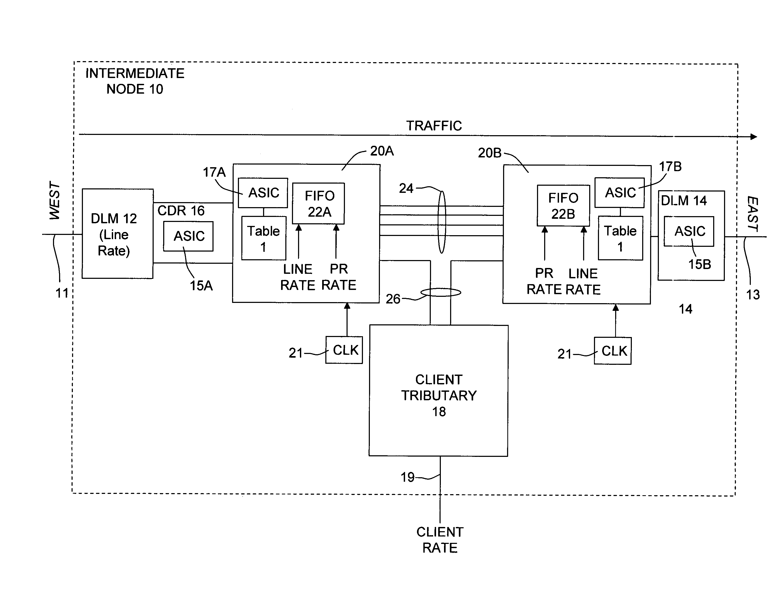
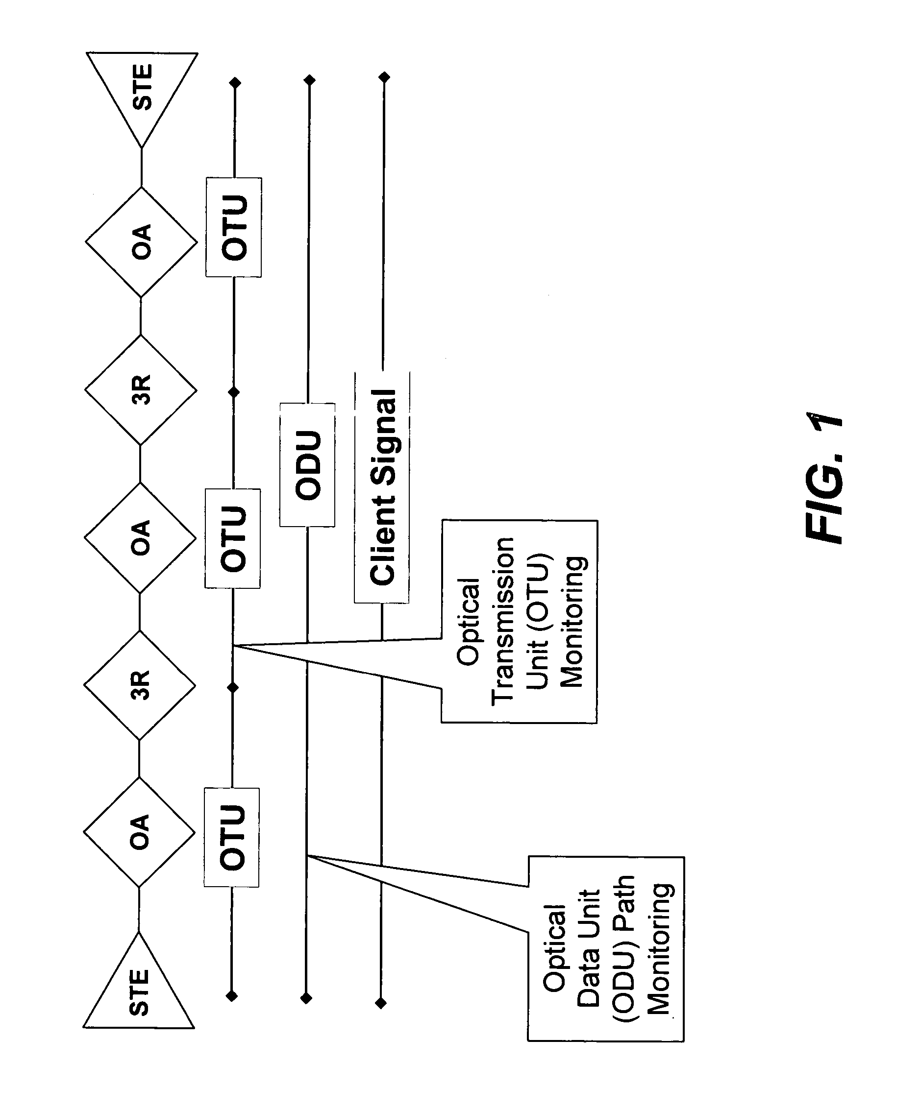
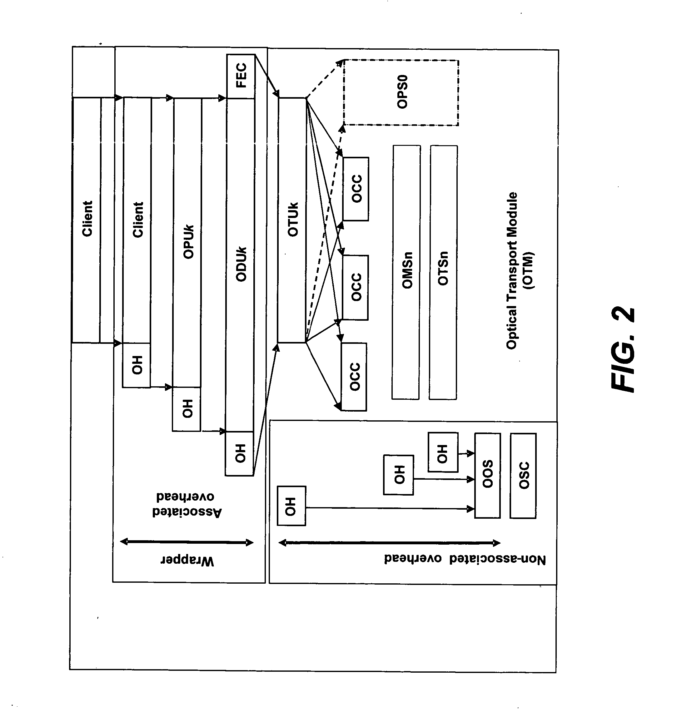
[0034]Reference is initially made to what is called a digital optical network which is described in U.S. patent application Ser. No. 10 / 267,212, filed Oct. 8, 2002, entitled, DIGITAL OPTICAL NETWORK ARCHITECTURE, which is owned by the assignee herein and is incorporated herein by its reference. Such a network is inherently asynchronous, and makes extensive use of OEO conversions at signal regeneration nodes in the network to provide “3R” functionality which deals with any electronic signal reconditioning to correct for transmission impairments as well as 3R processing, such as, for example, but not limited to, FEC encoding, decoding and re-encoding, in addition to signal re-amplification (1R), signal reshaping (2R) and signal retiming (3R). In both of these respects (i.e., asynchronous operation and signal reconditioning), this network architecture partially runs counter to key architectural principles embodied in the ITU-T OTN architecture in general, and to the G.709 standard laye...


PUM


Abstract

An optical transmission network is inherently asynchronous due to the utilization of a variable overhead ratio (V-OHR). The network architecture makes extensive use of OEO regeneration, i.e., deals with any electronic reconditioning to correct for transmission impairments, such as, for example, FEC encoding, decoding and re-encoding, signal reshaping, retiming as well as signal regeneration. The optical transmission network includes a plesiochronous clocking system with intermediate nodes designed to operate asynchronously with a single local frequency clock without complicated network synchronization schemes employing high cost clocking devices such as phase locked loop (PLL) control with crystal oscillators and other expensive system components. The asynchronous network operation provides for asynchronous remapping or remapping of any client signal utilizing any type of transmission protocol where the line side rate or frequency is always the same frequency for the payload signal and the local frequency at an intermediate node is set to a local reference clock in accordance with the payload type and its overhead ratio, i.e., the overhead ratio is varied to meet the desired difference between the line rate or frequency and the desired client signal payload rate or frequency for the particular client signal payload type.

Description

REFERENCE TO RELATED APPLICATIONS[0001]This application claims priority to prior provisional patent application Ser. No. 60 / 427,159, filed Nov. 18, 2002, which provisional patent application is incorporated herein by its reference.BACKGROUND OF THE INVENTION[0002]1. Field of the Invention[0003]This invention relates generally to asynchronous clock operation in optical transmission networks and more particularly to the deployment of asynchronous operation for an optical transport network (OTN) designed to operate asynchronously by means of mapping and remapping of client signal overhead or 10GbE signal protocol where the line rate, however, is maintained constant throughout signal transport.Introduction[0004]As used herein, the terms “rate” and “frequency” are to have the same meaning. Also, there is discussion about deployment of the invention herein in end terminals and intermediate nodes of transmission network, in particular as exemplified in optical transmission systems followin...

Claims


Application Information

Patent Timeline
Patent Type & Authority Patents(United States)
IPC IPC(8): H04L12/56H04J3/06H04J3/07H04J3/16H04L1/00H04L5/22H04Q11/04
CPCH04J3/07H04L1/0057H04J3/1652H04J3/1611H04J3/0691H04J2203/0085
Inventor PERKINS, DREW D.CHIANG, TING-KUANGSPRAGUE, EDWARD E.MURPHY, DANIEL P.
Owner INFINERA CORP
Why Eureka
Try Eureka