Fuel analysis system

a fuel analysis and fluorescence technology, applied in the field of xray fluorescence (xrf) systems, can solve the problems of relatively expensive systems, affecting the detection accuracy of catalyst fines, so as to reduce the background signal of exciting radiation, improve the detection accuracy, and reduce the effect of catalyst fines

Active Publication Date: 2007-10-23
OLYMPUS AMERICA
View PDF3 Cites 19 Cited by
  • Summary
  • Abstract
  • Description
  • Claims
  • Application Information

AI Technical Summary

Benefits of technology

[0012]It is a further object of this invention to provide such an analysis system which limits the excitation of sulfur in the fuel oil sample and reduces the background signal of the exciting radiation.
[0013]It is a further object of this invention to provide such a system which is ergonomic and robust in design.
[0014]The subject invention results from the realization that an erg

Problems solved by technology

The presence of high (>80 ppm) levels of aluminum and silicon and other catalyst fines in the fuel can cause problems when the fuel is injected into the engine.
The catalyst fines are very hard materials which can cause rapid wear on the engine components such as the cylinder, pistons and valves.
The major drawbacks of ICP for testing in the field (e.g., on-ship or dockside) are that such systems are relatively expensive instruments that use expensive consumables such as liquid Argon, and are not portable.
In addition this method is time consuming and requires several analytical steps that require a skilled technician to carry out the procedure.
Hence, there are several technological problems wh

Method used


Image

  • Fuel analysis system
  • Fuel analysis system
  • Fuel analysis system

Examples


Embodiment Construction

[0028]Aside from the preferred embodiment or embodiments disclosed below, this invention is capable of other embodiments and of being practiced or being carried out in various ways. Thus, it is to be understood that the invention is not limited in its application to the details of construction and the arrangements of components set forth in the following description or illustrated in the drawings. If only one embodiment is described herein, the claims hereof are not to be limited to that embodiment. Moreover, the claims hereof are not to be read restrictively unless there is clear and convincing evidence manifesting a certain exclusion, restriction, or disclaimer.

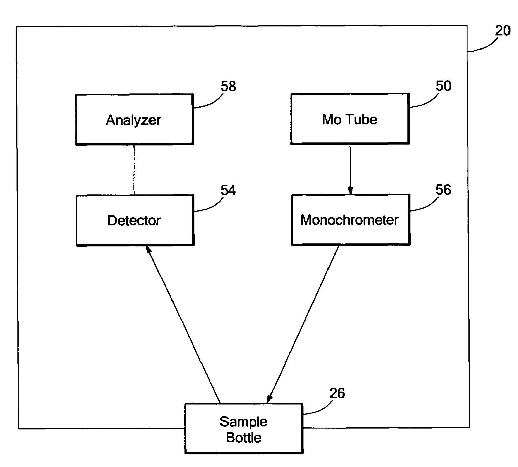
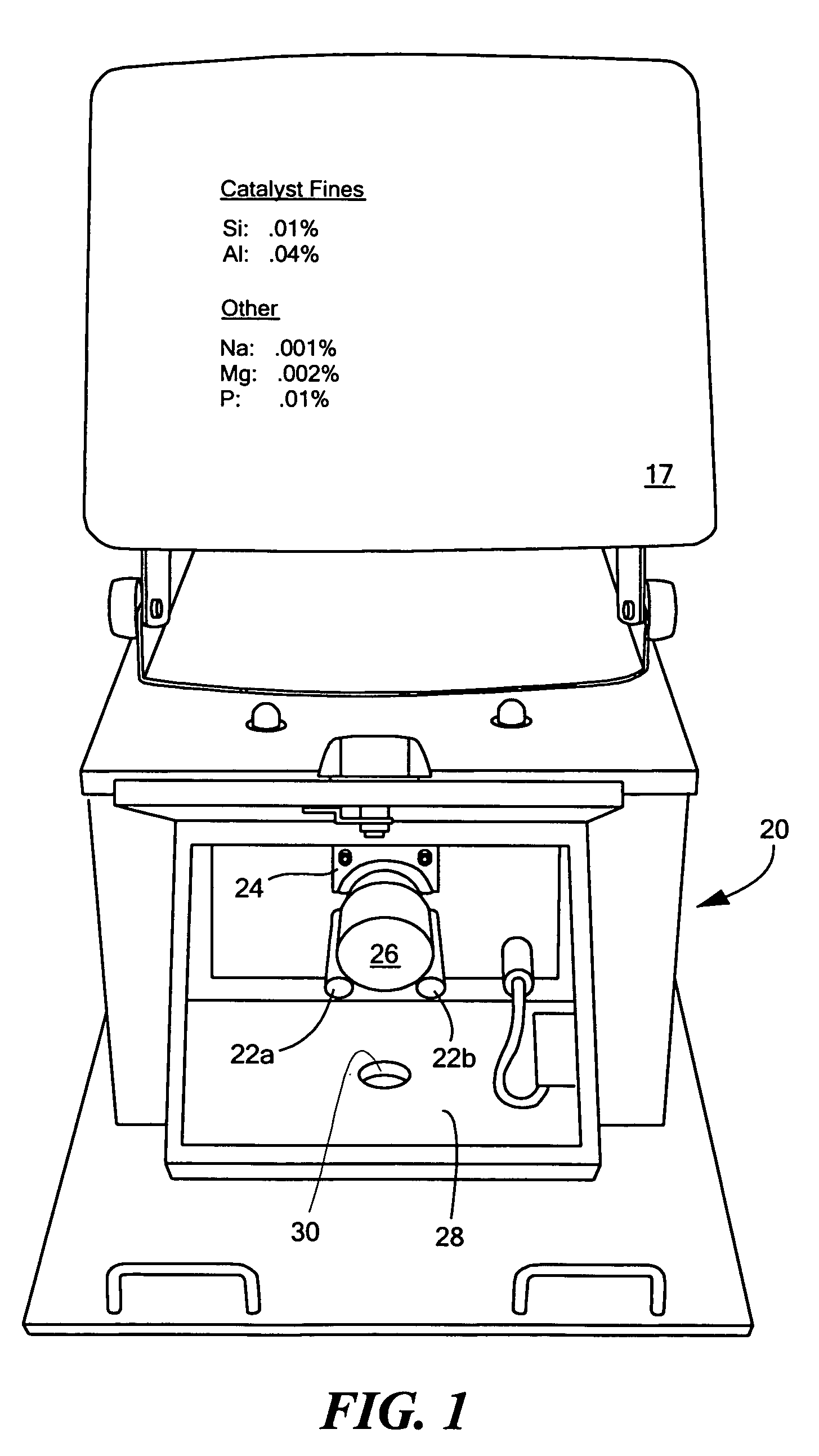
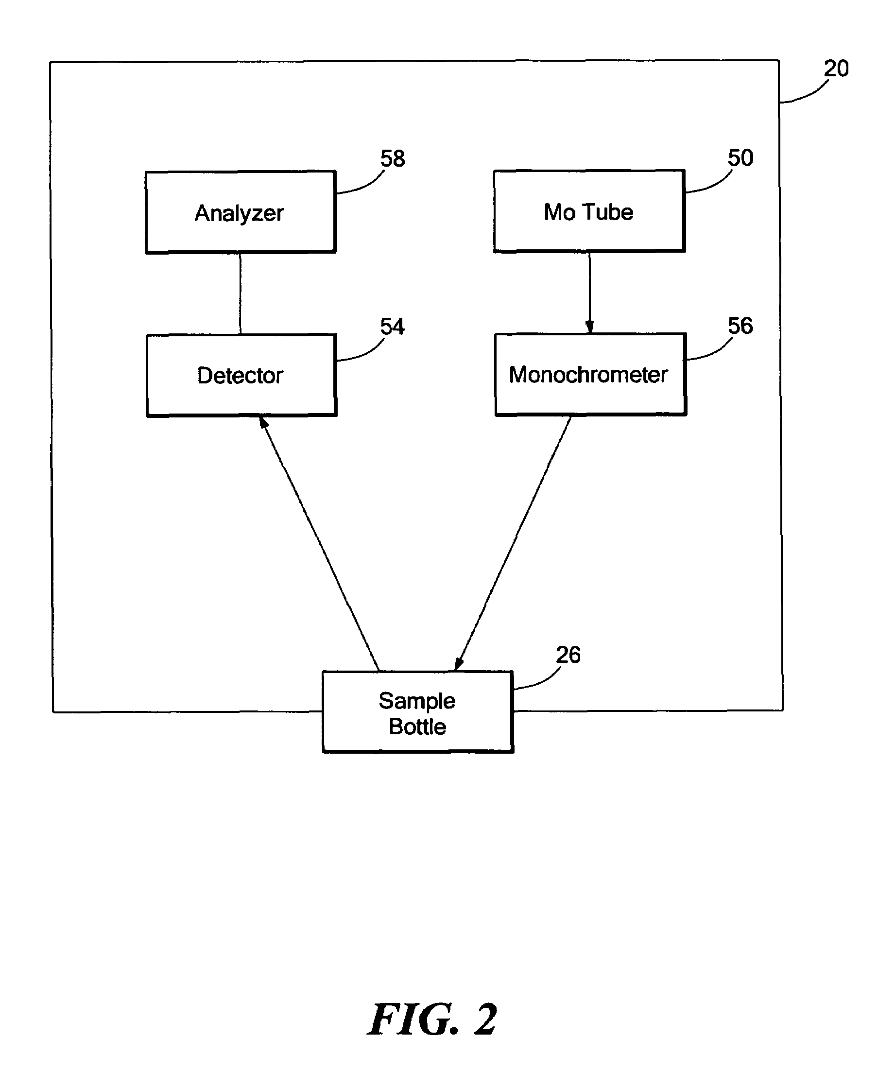
[0029]FIG. 1 is a depiction of one example of an XRF system in accordance with this invention engineered to detect and measure the concentrations of catalyst fines in a fuel oil sample. In one preferred embodiment, a sample holder includes posts 22a and 22b and sample adapter 24 which position sample holder 26 within unit 2...


PUM


Abstract

A fuel analysis system and method wherein an x-ray source emits x-rays at an energy level below but proximate the absorption edge of sulfur. A monochromator is in the optical path between the source and a fuel sample for directing x-rays at a single energy level at the fuel sample to limit excitation of any sulfur in the fuel sample. A detector is responsive to x-rays emitted by the sample and an analyzer is responsive to the detector and configured to determine the amount of silicon and aluminum in the sample.

Description

FIELD OF THE INVENTION[0001]This subject invention relates to an x-ray fluorescence (XRF) system and, more particularly, to such a system well suited to measure the concentrations of catalyst fines in fuel oil.BACKGROUND OF THE INVENTION[0002]Crude oil is processed by a variety of means to produce the valuable light fractions such as gasoline, kerosene, and the like. Since these products are valuable commodities, it makes economic sense to try and convert as much of the oil as possible to these components. As much as 75% of a barrel of oil can be utilized in this way by a combination of distillation and catalytic cracking. In catalytic cracking, the heavy oil components which were left over from distillation are broken into smaller molecular weight components with the aid of a cracking catalyst. The catalysts are porous aluminum-silicate structures. At the end of the cracking process the material which was not broken down remains in the product. The sludge oil contains significant a...

Claims


Application Information

Patent Timeline
IPC IPC(8): G01N23/223
CPCG01N23/223G01N33/287G01N2223/076G01N33/2835
Inventor HARDMAN, PETER JOHNHUBBARD-NELSON, BRADLEY
Owner OLYMPUS AMERICA
Why Eureka
Try Eureka