
Process for making diaryl carbonate

a diaryl carbonate and process technology, applied in the field of diaryl carbonate production, can solve the problems of increasing the cost of the process, breaking the azeotropic mixture, and consuming energy and money

Active Publication Date: 2007-10-30
SHELL USA INC
View PDF12 Cites 39 Cited by
  • Summary
  • Abstract
  • Description
  • Claims
  • Application Information

AI Technical Summary

Benefits of technology

The present invention is a process for making diaryl carbonates by reacting aromatic hydroxy compounds with dialkyl carbonate in a series of fixed bed reactors. The process involves feeding the reactants to a distillation column, where they are contacted with a transesterification catalyst in one stage and a disproportation catalyst in another stage. The resulting product is then separated as bottoms and overheads. The invention allows for efficient use of the reactants, resulting in high conversion rates of the dialkyl carbonate and minimal byproduct formation. The use of specific catalysts and optimized reaction zones along the distillation column further enhance the efficiency of the process.

Problems solved by technology

Therefore, the recovery of dimethyl carbonate in the mixture involves breaking the azeotropic mixture which is energy consuming and expensive.
Pressure and reflux ratio can be adjusted to effect the reaction zone temperature profile and / or reaction volume can be increased but such changes can increase the cost of the process.
The patentee states, “While the dialkyl carbonate used as a starting material in the method of the invention may in theory be any dialkyl carbonate, it will be appreciated that in practice it will be preferred to use a dialkyl carbonate with a small alkyl group, such as, for example dimethyl carbonate.” However, the methanol is the cause of the azeotrope problem and the solution merely changes the manner of breaking the azeotrope.
Also producing the dimethyl carbonate in the first place involves the same problem, i.e., breaking the azeotropic mixture to separate the product, dimethyl carbonate, from the product stream.

Method used


Image

  • Process for making diaryl carbonate
  • Process for making diaryl carbonate
  • Process for making diaryl carbonate

Examples


Embodiment Construction

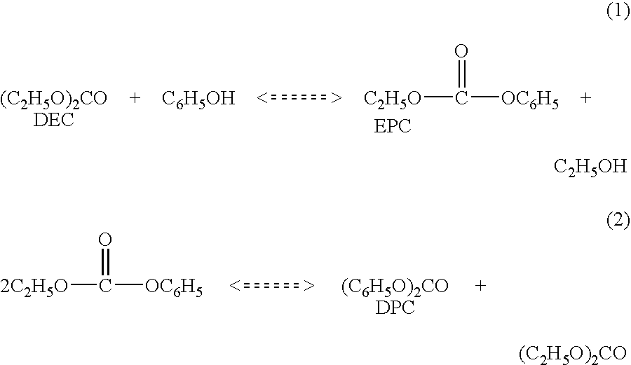
[0014]Diphenyl carbonate is produced in a two step reaction wherein phenol first reacts with diethyl carbonate in the presence of a transesterification catalyst to produce ethyl phenyl carbonate and ethanol (1). This is followed by a second step disproportionation reaction wherein ethyl phenyl carbonate is converted to diphenyl carbonate and diethyl carbonate(2). The net reaction products are diphenyl carbonate and ethanol.

[0015]

Typically the equilibrium constant for the first reaction is substantially less than one while that for the second reaction is somewhat greater than one. The first step can be carried out with equimolar amounts of phenol and diethyl carbonate or with and excess of either. In all cases the conversion of ethyl phenyl carbonate and diphenyl carbonate are impractically low, from the perspective of product recovery, at equilibrium.

[0016]Examples of organic carbonates produced by this invention are DPC (diphenyl carbonate), EPC (ethyl phenyl carbonate), MPC (methy...


PUM

PropertyMeasurementUnit
sizesaaaaaaaaaa
sizeaaaaaaaaaa
temperaturesaaaaaaaaaa

Abstract

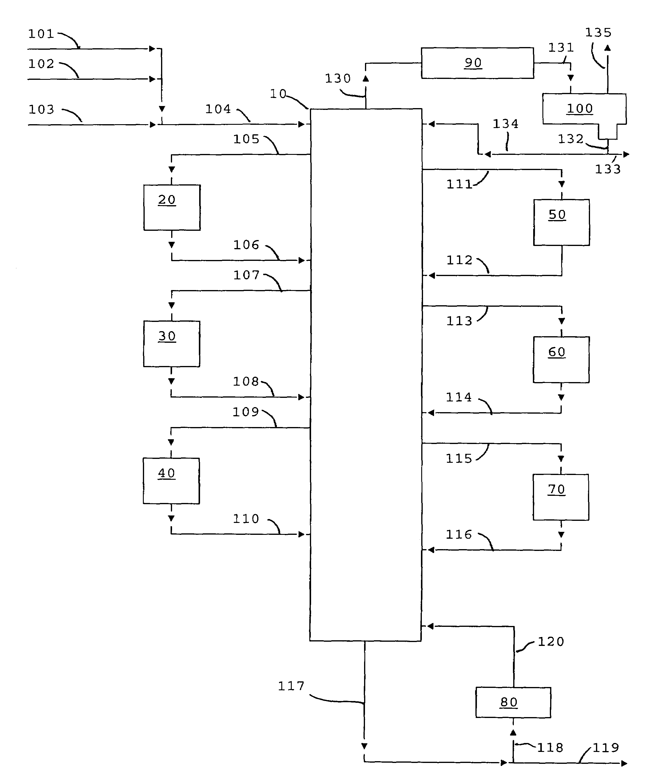
Diphenyl carbonate is produced by reacting phenol with diethyl carbonate in a series of fixed bed reactors each of which is connected at different position on a distillation column via side draw and return streams. The composition of material in a distillation column varies along the length of the column, which is predictable under a given set of conditions of temperature and pressure, thus withdrawing streams at different stages in the column, allows the reactor receiving the feed from a particular stage to be operated under conditions to maximize the desired reaction, while allowing the unreacted or byproduct to go back into the distillation and be sent to a stage (by the equilibrium of the distillation) where they are favorably treated in a reactor.

Description

BACKGROUND OF THE INVENTION[0001]1. Field of the Invention[0002]The present invention relates to a process for the production of diaryl carbonates, such as diphenyl carbonate. More particularly, the invention relates to a process for the production of diaryl carbonates wherein a series of fixed bed reactors withdraw feed from a single distillation column at different separation stages and return the product to the column. The reactors may be operated at different conditions than those of the distillation column to optimize production of diaryl carbonates.[0003]2. Related Art[0004]Diphenyl carbonate is a valuable intermediate for the production of polycarbonate. In current commercial practice, diphenyl carbonate is produced by transesterification with an alcohol followed by disproportionation using dimethyl carbonate (DMC) and phenol. Such processes are disclosed in U.S. Pat. Nos. 5,210,268; 6,197,918; and 6,262,210. The typical reaction is:[0005][0006]The unconverted dimethyl carbon...

Claims


Application Information

Patent Timeline
Patent Type & Authority Patents(United States)
IPC IPC(8): C07C69/96
CPCC07C68/06C07C68/08C07C69/96B01D3/009B01D3/143C07C2531/12
Inventor RYU, J. YONGGELBEIN, ABRAHAM P.
Owner SHELL USA INC
Learn More