
Motor driving apparatus

a technology for motor driving and motor components, applied in the direction of electric generator control, dynamo-electric converter control, dynamo-electric gear control, etc., can solve the problems of motor driving apparatus not meeting the harmonics standards of the international electrotechnical commission, increasing harmonic components, and increasing harmonics. , to achieve the effect of reducing the value of capacitors, minimizing the reduction of power factor, and reducing size and weigh

Inactive Publication Date: 2007-11-06
PANASONIC CORP
View PDF13 Cites 21 Cited by
  • Summary
  • Abstract
  • Description
  • Claims
  • Application Information

AI Technical Summary

Benefits of technology

[0023]The present invention is made to solve the above-described problems. Accordingly, an object of the present invention is to provide a motor driving apparatus satisfying the IEC harmonics standards, that can minimize reduction in the power factor due to waveform distortion of the current supplied from the power supply by controlling the motor driving current or motor driving voltage, thereby to minimize the reactance which is required for the circuit construction, especially, the capacitor reactance, and moreover, that can carry out control of the motor driving current or voltage by a relatively simple construction so as to maintain high efficiency of motor drive and effectively minimize reduction in the power factor.

Problems solved by technology

In the conventional motor driving apparatus so constructed, the smoothing capacitor and the power-factor improvement reactor have large capacitances, resulting in problems in the cost, lifetime, efficiency, weight, size, and the like of the motor driving apparatus.
In other words, in the motor driving apparatus, when the values of the smoothing capacitor and the reactor become small, the power factor is degraded due to distortion in the waveform of the current that flows from the power supply to the motor driving apparatus, leading to an increase in harmonic components.
As a result, the motor driving apparatus cannot satisfy the IEC (International Electrotechnical Commission) harmonics standards.
As a result, the level of the input voltage of the inverter circuit 4 is lowered, and a desired voltage to be applied to, for example, a brushless DC motor, cannot be obtained.
Therefore, satisfactory effects of power factor improvement cannot be obtained by only modulating the motor driving current so that the waveform thereof becomes equal to the waveform of the input power supply voltage by using the absolute value of the inputted power supply voltage.
Moreover, control of the motor driving current is very complicated, that is, control of the motor driving current comprises the steps of calculating the current command value io on the basis of the DC link current idc and the modulated waveform of the command torque To, and adjusting the gate signal Sg to be applied to the inverter circuit 4 so as to eliminate a deviation between the calculated current command value io and the actual driving current i.
Furthermore, since the motor driving current is vigorously modulated by using the output waveform of the AC power supply, the output torque of the motor is also modulated by the output waveform of the AC current supply, resulting in a possibility that significant noise and vibration might occur in a high-load area.
As a result, an AD converter for detecting an analog value and a microcomputer for detecting the instantaneous value on the basis of the output of the AD converter are required, leading to an increase in cost.
However, this leads to a reduction in efficiency of the motor.
At this time, advancing the output voltage of the inverter circuit leads to an increase in the phase difference between the output current and the output voltage, resulting in a reduction in the motor driving efficiency.
Moreover, advancing the phase of the output voltage of the inverter circuit to prevent saturation of the output voltage is technically very difficult.
Further, the second prior art has the following fundamental problem.
As a result, there is a possibility that the regenerative current cannot be stopped.
Moreover, since, during this regeneration period, no current is supplied from the single-phase AC power supply to the inverter circuit, the current waveform of the single-phase AC power supply is distorted, resulting in a reduction in the input power factor of the inverter circuit.

Method used


Image

  • Motor driving apparatus
  • Motor driving apparatus
  • Motor driving apparatus

Examples


first embodiment

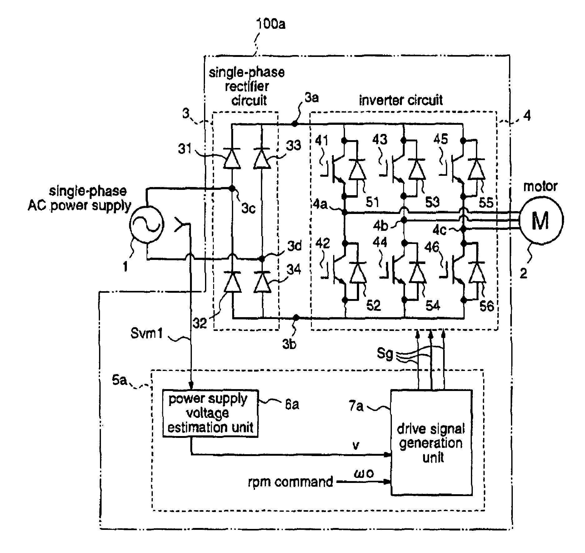
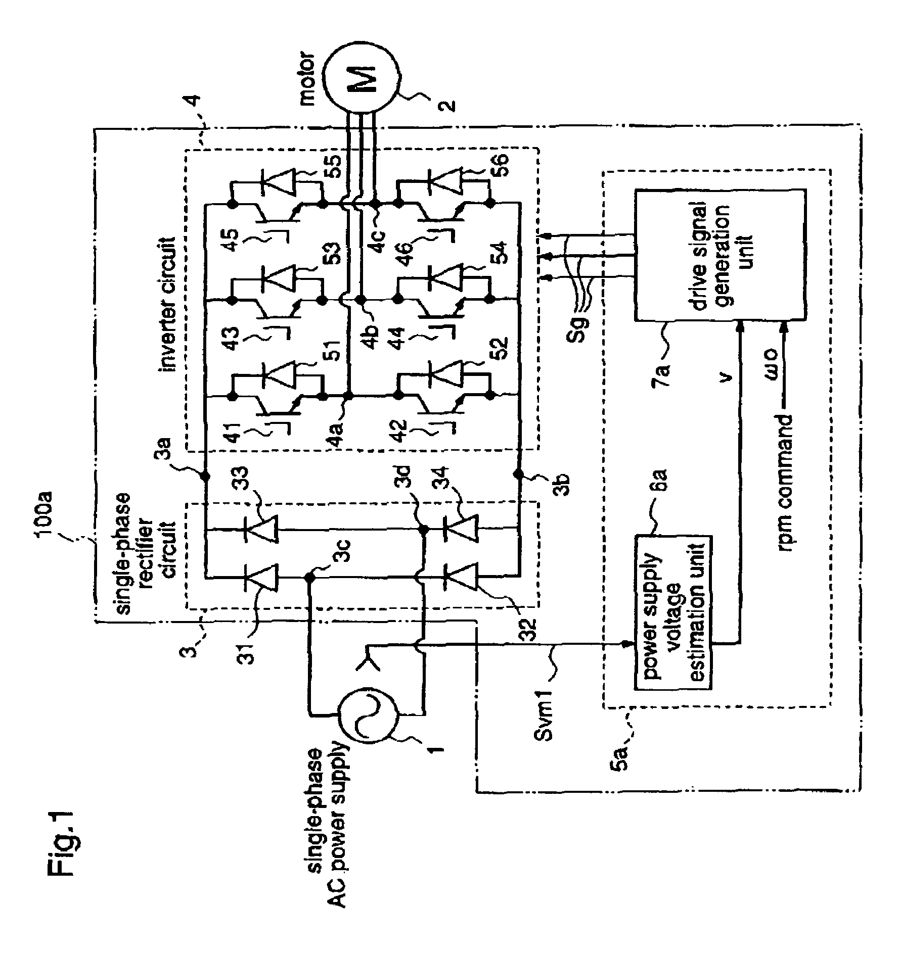
[0065]FIG. 1 is a block diagram for explaining a motor driving apparatus according to a first embodiment of the present invention.

[0066]A motor driving apparatus 100a according to the first embodiment has an input connected to a single-phase AC power supply 1, and drives a motor 2 at a desired frequency by using a three-phase DC output. In this first embodiment, the motor 2 may be any of an induction motor, a DC brushless motor, a reluctance motor, and the like. Further, it is assumed that the motor driving apparatus 100a drives a motor of a compressor for circulating a refrigerant, which is mounted on an air conditioner.

[0067]Hereinafter, a single-phase rectifier circuit 3, an inverter circuit 4, and an inverter control unit 5a, which are constituents of the motor driving apparatus 100a, will be described in detail.

[0068]The single-phase rectifier circuit 3 receives an output of the single-phase AC power supply 1, and supplies a DC voltage to the inverter circuit 4. The inverter ci...

second embodiment

[0102]FIG. 3 is a block diagram for explaining a motor driving apparatus according to a second embodiment of the present invention.

[0103]A motor driving apparatus 100b according to the second embodiment has an input connected to a single-phase AC power supply 1, and drives a motor 2 at a required frequency by using a three-phase AC output. The motor driving apparatus 100b includes a single-phase rectifier circuit 3 connected to the single-phase AC power supply 1, an inverter circuit 4 that is connected to the single-phase rectifier circuit 3 and outputs a driving current and a driving voltage to the motor 2, and an inverter control unit 5b for controlling the inverter circuit 4.

[0104]The single-phase rectifier circuit 3 and the inverter circuit 4 included in the motor driving apparatus 100b according to the second embodiment are identical to those of the motor driving apparatus 100a according to the first embodiment.

[0105]Hereinafter, the inverter control unit 5b of the motor drivin...

third embodiment

[0130]FIG. 4 is a block diagram for explaining a motor driving apparatus according to a third embodiment of the present invention.

[0131]A motor driving apparatus 100c according to the third embodiment has an input connected to a single-phase AC power supply 1, and drives a DC brushless motor 9 by a three-phase AC output at a required frequency.

[0132]Hereinafter, a single-phase rectifier circuit 3, an inverter circuit 4, and an inverter control circuit 5c that constitute the motor driving apparatus 100c will be described in detail.

[0133]The single-phase rectifier circuit 3 and the inverter circuit 4 are identical to those of the motor driving apparatus 100b according to the second embodiment.

[0134]The inverter control unit 5c supplies the inverter circuit 4 with a drive signal Sg so that the DC brushless motor 9 is driven at a rpm required by the user. The inverter control unit 5c comprises a power supply voltage estimation unit 6a, an inverter input voltage detection unit 8, and a d...


PUM


Abstract

A motor driving apparatus for driving a motor includes a single-phase rectifier circuit having an input connected to a single-phase AC power supply, an inverter circuit that is connected to the single-phase rectifier circuit and applies a current and a voltage to the motor, and an inverter control unit for controlling the inverter circuit. The inverter control unit controls the current applied to the motor, i.e., the output of the inverter circuit, so that the inverter input voltage becomes equal to the absolute value of the voltage of the single-phase AC power supply.

Description

FIELD OF THE INVENTION[0001]The present invention relates to a motor driving apparatus and, more particularly, to a motor driving apparatus for driving a motor by a system comprising a single-phase rectifier circuit and an inverter.BACKGROUND OF THE INVENTION[0002]A conventional motor driving apparatus drives a motor by using a common system comprising a single-phase rectifier circuit and an inverter. The single-phase rectifier circuit has a reactor for improving a power factor (not shown), and a smoothing capacitor for smoothing an output voltage of the single-phase rectifier circuit.[0003]In the conventional motor driving apparatus so constructed, the smoothing capacitor and the power-factor improvement reactor have large capacitances, resulting in problems in the cost, lifetime, efficiency, weight, size, and the like of the motor driving apparatus. The large-capacitance smoothing capacitor and the large-capacitance reactor are employed to prevent degradation in the power factor d...

Claims


Application Information

Patent Timeline
IPC IPC(8): H02P21/00H02P27/06H02M1/42H02M5/45H02M5/458H02P6/00H02P6/08H02P6/18H02P27/04
CPCH02M1/425H02P27/042H02M5/458Y02B70/126H02P27/048Y02B70/10A47J31/50A47J31/06A47J31/54A47J31/4403
Inventor UEDA, MITSUONAKATA, HIDEKI
Owner PANASONIC CORP
Learn More