Method for simultaneous removal of asphaltene, and/or paraffin and scale from producing oil wells

a technology of asphaltene and paraffin, which is applied in the direction of well accessories, transportation and packaging, sealing/packing, etc., can solve the problems of affecting the effectiveness and affecting the efficiency of well production, and requiring extensive well shutdown time, so as to increase the output flow of well, and increase the effect of well outpu

Active Publication Date: 2007-11-20
DYER RICHARD J
View PDF10 Cites 17 Cited by
  • Summary
  • Abstract
  • Description
  • Claims
  • Application Information

AI Technical Summary

Benefits of technology

[0022]In accordance with one embodiment of the present invention, it is an object thereof to provide an improved method for removing foreign matter from a well to increase the output flow of the well.
[0023]It is another object of the present invention to provide an improved method in combination with a unique apparatus to clean the bore hole of the well to increase the output flow of the well.
[0024]It is still another object of the present invention to provide a one step process to simultaneously remove the asphaltene and / or paraffin and scale and thus clean the bore hole of the well to increase the output flow of the well that is less expensive and easier to use than prior art methods and devices.BRIEF DESCRIPTION OF THE PREFERRED EMBODIMENTS
[0026]In accordance with another embodiment of the present invention, the emulsion is injected into said oil well through the use of a combination surge and pressure wash tool. The combination pressure and surge wash tool has a nipple assembly, and a by-pass port is coupled to the nipple assembly. A diverter cup is coupled to the by-pass port. A plurality of pressure wash cups are positioned on the tool. A pressure wash port is located between the plurality of pressure wash cups. A pump shoe assembly is coupled to a bottom pressure wash cup. After the emulsion is injected into the well and is there for a short period of time, the surge and pressure wash tool is coupled to a tubing string of the oil well; the surge and pressure wash tool is then moved to the bottom of the oil well and then raised in repeat fashion.

Problems solved by technology

Paraffin and / or asphaltene and scale formation in producing oil wells, and particularly those wells producing high-paraffin containing oils, significantly interferes with the effectiveness and efficiency of the well production.
Generally, the paraffin and / or asphaltene crystallizes out of and solidifies in the well bore, the area surrounding the well bore, the casing and tubing of the well thereby blocking further production.
The cutting procedure is a relatively crude procedure and requires extensive well shutdown time.
Moreover, it is extremely inefficient inasmuch as substantial amounts of paraffin and / or asphaltene remain in the well.
This is an expensive method since the crude must be put through a heater treater along with a demulsifier in order to facilitate the removal of solids and water therefrom.
Another disadvantage to this method is that in many instances, 100% of the fluid injected is not recovered and thus some is lost to the reservoir.
Moreover, this technique is very dangerous, particularly with wells producing a crude having a low flash point.
Indeed, such wells cannot be hot-oiled because the auto-ignition temperature of the oil is so low.
Thus, bringing the oil in direct contact with a heating mechanism creates a substantial fire hazard.
However, while this mixture may have some effect on the removal of carbonate scale build-up in wells, it has not presented a satisfactory answer to paraffin and / or asphaltene removal.
An additional disadvantage of each of the above methods is due to the fact that normally it is desirable to subject a well to acidization at some subsequent point in time after the paraffin and / or asphaltene removal.
This is a disadvantageous situation for subsequent acidization.
The acid solution is aqueous and, if the interior portions and mechanical elements of the well are oil wet, direct contact of these surfaces with the acid solution is inhibited making the acidization treatment much less effective.
This is not desirable since the reactions themselves create safety hazards and the paraffin still remains.
This has the disadvantage of numerous steps and the use of electrical charge.
The problems associated with the prior art set forth above are the use of numerous steps to remove paraffin, asphaltene, sludge, scale and / or other undesired materials from the wells and the fact that these multistep procedures are expensive and not efficient.

Method used


Image

  • Method for simultaneous removal of asphaltene, and/or paraffin and scale from producing oil wells
  • Method for simultaneous removal of asphaltene, and/or paraffin and scale from producing oil wells

Examples


example 1

Preparation of the aqueous cleaning emulsion

[0098]Seven pounds of conditioned water (prepared by passing through a CARE FREE water conditioner) are added to seven pounds of detergent (CHAMPION'S WATERLESS hand cleaner) and mixed together. This mixture was then mixed together with 40 pounds of kerosene and the resultant materials were blended together for a period of 10 minutes. Another 40 pounds of kerosene was added to the above mixture and again blended for an additional 10 minutes. At the end of this time, additional kerosene was added until the liquid forms an emulsion. This emulsion was blended for an additional 5 minutes. The emulsion was saturated with kerosene, was water soluble and had the thickness of a milk shake.

[0099]Into a 225 gallon tank, there was added 8 gallons of said emulsion and then 100 gallons of catalytic conditioned water was introduced by the use of a nozzle attached to the end of the conditioned water hose. The fluid in the tank was further mixed by circul...

example 2

Treating Oil Wells with the Emulsion

[0100]Using the procedure set forth in Example 1, six batches of emulsion were prepared and used to treat six individual partially / fully plugged oil wells in the Midway Sunset Field near Taft, Calif.

[0101]In each case, the emulsion from the 225 gallon tank was pumped into the well bore through the annuli thereof. After the emulsion was emptied from the tank, 40 gallons of conditioned water was pumped into the well. The emulsion in the well bore was allowed to circulate for 72 hours and then high pressure steam was used to displace said emulsion from the well bore into the surrounding geological formulations. Each well was placed back in operation / production. The average production increase was 34 barrels per day / 6 wells or an average of 5.67 barrel increase / day / well.

example 3

Treating Oil Wells with the Emulsion in Combination with Surge / Pressure Wash Tool

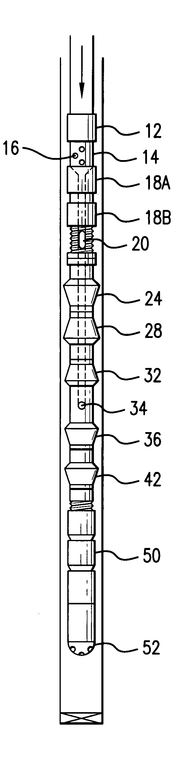
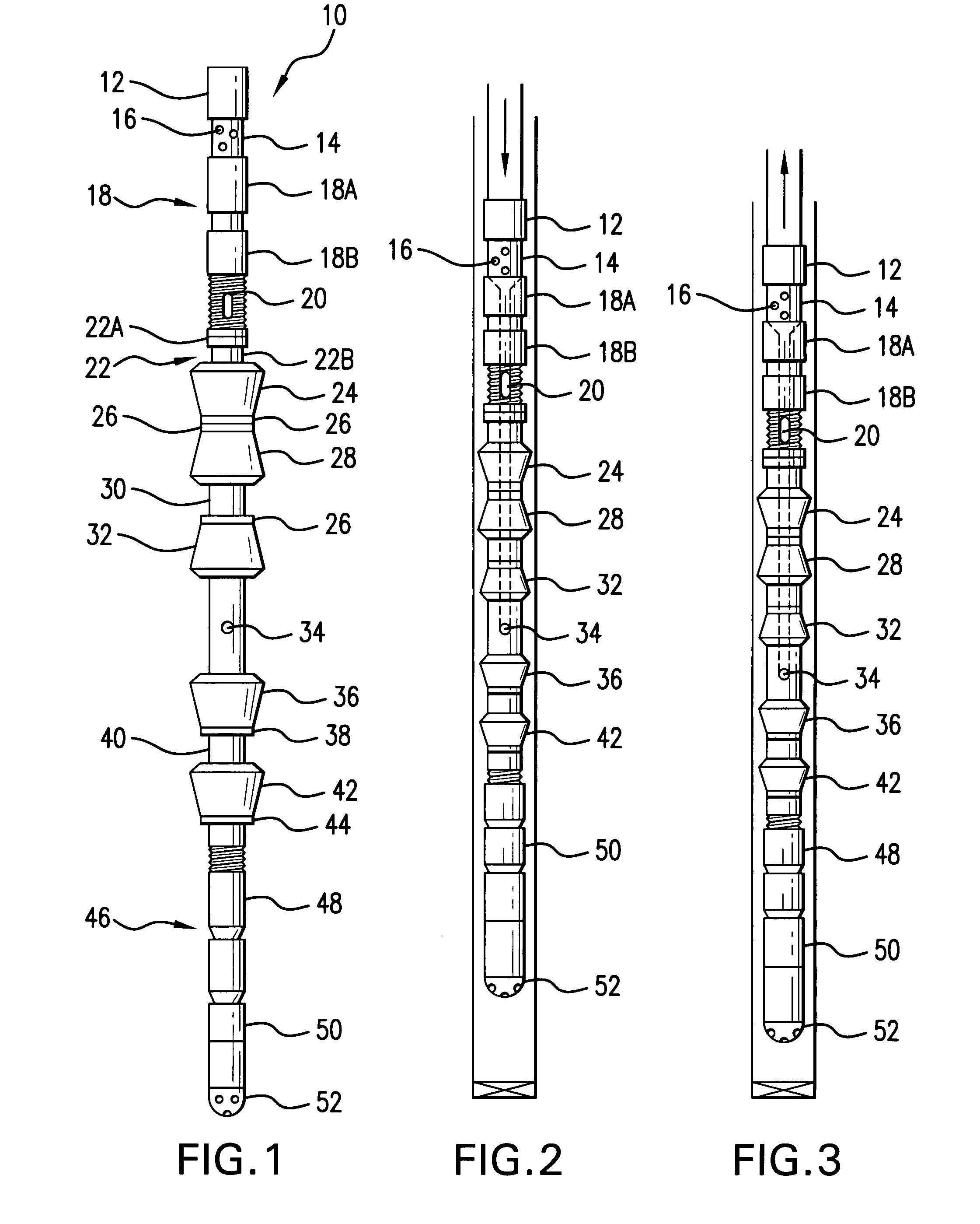
[0102]Following the procedures set forth in Examples 1 and 2, the well was not returned to production, and the emulsion remained in the well. The surge / pressure wash tool was placed at the end of the tubing string and run into the well. Then an additional 100 barrels of emulsion fluid was allowed to gravity flow into the well through the annulus valve in the well head. The emulsion followed the wash tool down the well. When the wash tool reached the slotted liner or the perforated zone, the wash tool began to float indicating the well was still plugged. After a short time the wash tool reached the bottom of the well. Then it was moved up and down the length of the derrick (45 feet) thus promoting a suction in the upward movement of the wash tool, below the wash tool. The tubing string and wash tool on its own weight returns to the bottom of the well. The emulsion entered the tubing string and wash tool ...


PUM

PropertyMeasurementUnit
distanceaaaaaaaaaa
period of timeaaaaaaaaaa
distanceaaaaaaaaaa

Abstract

A method for cleaning oil wells to increase the flow of oil thereof by use of a unique aqueous cleaning emulsion comprising of water, hydrocarbon solvent, detergent and mineral acid. This one step method provides for the simultaneously cleaning / removal of asphaltine and / or paraffin and scale. This method can be used alone or with the assistance of a wash tool which is a combination pressure and surge wash tool having a nipple assembly. A by-pass port is coupled to the nipple assembly and a diverter cup is coupled to the by-pass port. A plurality of pressure wash cups are positioned on the tool. A pressure wash port is located between the plurality of pressure wash cups and a pump shoe assembly is coupled to a bottom pressure wash cup.

Description

BACKGROUND OF THE INVENTION[0001]1. Field of the Invention[0002]This invention relates to oil and gas production wells and particularly to methods of simultaneously removing asphaltene and / or paraffin and scale from such wells.[0003]2. Description of the Prior Art[0004]Paraffin and / or asphaltene and scale formation in producing oil wells, and particularly those wells producing high-paraffin containing oils, significantly interferes with the effectiveness and efficiency of the well production. In severe cases, the presence of paraffin and / or asphaltene and scale, can, in essence, cause the oil production for a given well to cease.[0005]Generally, the paraffin and / or asphaltene crystallizes out of and solidifies in the well bore, the area surrounding the well bore, the casing and tubing of the well thereby blocking further production.[0006]In the past, attempts have been made to remove the paraffin and / or asphaltene by mechanically cutting it out of the well or using a so-called “hot-...

Claims


Application Information

Patent Timeline
Patent Type & Authority Patents(United States)
IPC IPC(8): E21B37/00E21B37/08C09K23/00
CPCC09K8/524E21B37/00E21B37/08Y10S507/93Y10S507/931
Inventor DYER, RICHARD J.
Owner DYER RICHARD J
Why Eureka
Try Eureka