Systems and methods for providing optimized patch antenna excitation for mutually coupled patches

a patch antenna and excitation technology, applied in the field of antennas, can solve the problems of limited insight into the radiation mechanism, low efficiency, low power, etc., and achieve the effects of enhancing radiation, improving efficiency, and particular susceptibility of array elements

Inactive Publication Date: 2007-11-20
THE TRUSTEES OF COLUMBIA UNIV IN THE CITY OF NEW YORK
View PDF19 Cites 86 Cited by
  • Summary
  • Abstract
  • Description
  • Claims
  • Application Information

AI Technical Summary

Benefits of technology

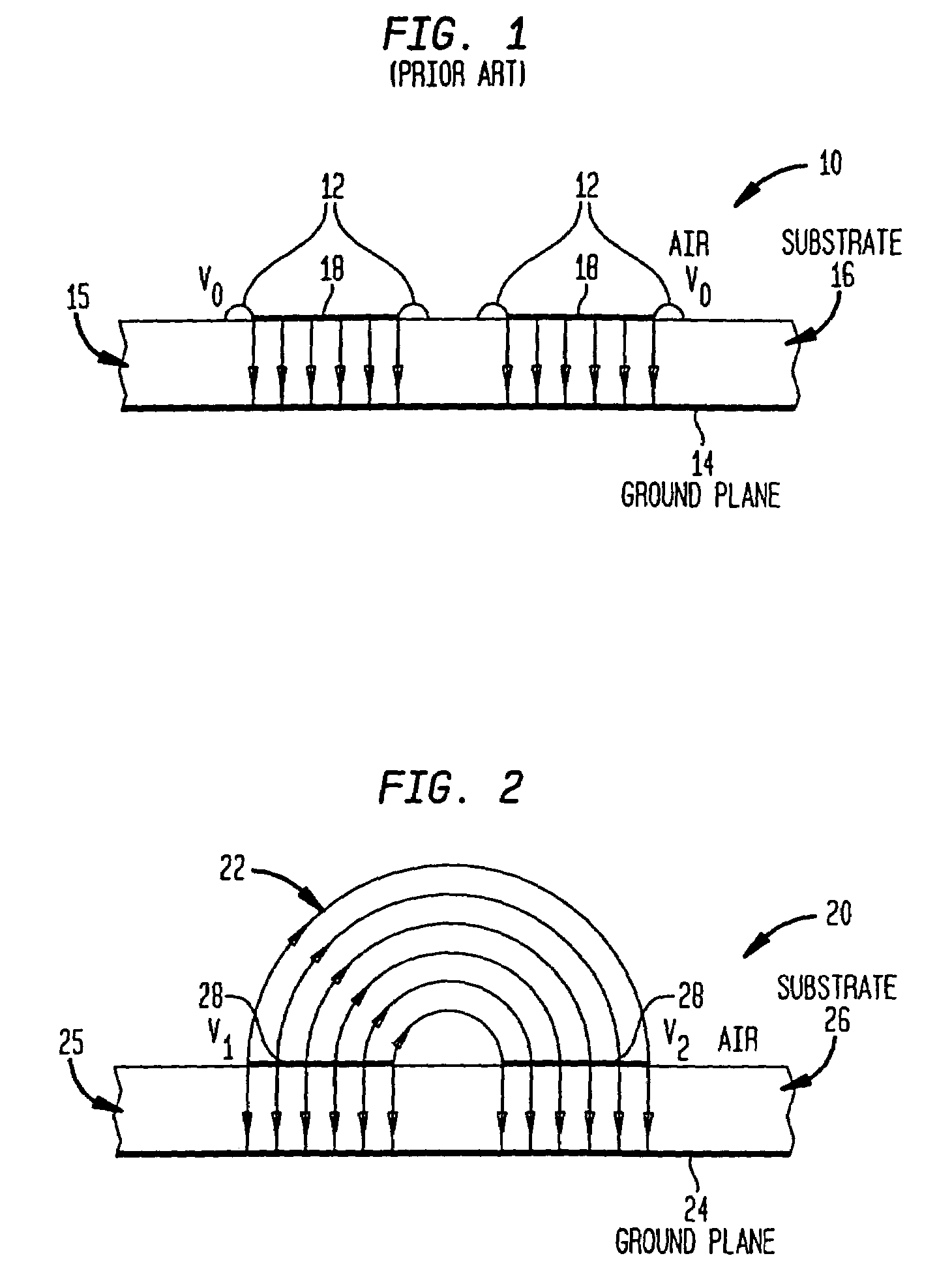
[0009]The present invention is generally directed to antennas comprising an array of radiating elements, and methods for exciting the array elements in a manner that exploits the mutual coupling effects between the elements. More particularly, the present invention relates to systems and methods for providing differential-mode excitation of microstrip patch antennas and monolithic microwave integrated circuit (MMIC) antenna arrays. It is an objective of the present invention to devise and prescribe differential-mode excitation methods, which impose different radio frequency (RF) voltages or currents at the different array elements (e.g., patches), to thereby generate and emit radiation from substantially the entire top surfaces of the patches, rather than merely from their edges, thereby enhancing the radiation and improving efficiency. Indeed, differential-mode excitation methods according to the invention are employed to operate an antenna array in a manner that exploits the particular susceptibility of array elements to mutual coupling effects such that the array radiates copiously from the top surfaces of the patches instead of merely from their edges.

Problems solved by technology

However, these methods offer limited insight into the radiation mechanism.
Microstrip patch antennas commonly exhibit disadvantageous operational characteristics such as low efficiency, low power, narrow bandwidth, and poor scanning performance.
Further, patch antennas are typically excited in an asymmetric manner to generate high-order modes of the dielectric substrate, which adds to the complexity of the electrical feed circuitry.

Method used


Image

  • Systems and methods for providing optimized patch antenna excitation for mutually coupled patches
  • Systems and methods for providing optimized patch antenna excitation for mutually coupled patches
  • Systems and methods for providing optimized patch antenna excitation for mutually coupled patches

Examples


Embodiment Construction

[0031]The following detailed description of preferred embodiments is divided into the following sections for ease of reference. Section I provides a general overview of features and advantages of an antenna array that operates under differential-mode excitation according to the invention. Section II provides a detailed discussion of preferred and exemplary embodiments of systems and methods for providing differential-mode excitation of an antenna array according to the invention. Section III discusses various embodiments for feeding voltages or currents to an antenna array for operating the antenna array in differential-mode. Section IV provides a detailed discussion of a method for determining the radiation from an array of patch antennas in differential-mode operation, wherein a model is developed to determine the field structure in the air space above a patch antenna array when operating in differential-mode.

I. General Overview

[0032]The present invention exploits the discovery th...


PUM


Abstract

An antenna array (e.g., microstrip patch antenna) operates in a manner that exploits the particular susceptibility of the mutual coupling effects between radiating elements in the array. Various differential-mode excitation schemes are provided for determining optimal differential-mode voltages or optimal differential-mode currents that are applied to the radiating elements (e.g., microstrip patches) to thereby achieve certain desirable radiation characteristics including, for example, aiming a radiated beam in a prescribed direction, steering the beam, shaping the radiated beam, and / or optimizing the gain of the antenna in a specified direction.

Description

CROSS-REFERENCE TO RELATED APPLICATIONS[0001]This application claims priority to U.S. Provisional Application Ser. No. 60 / 316,628, filed on Aug. 31, 2001, and to U.S. Provisional Application Ser. No. 60 / 343,497, filed Dec. 21, 2001, and to U.S. patent application Ser. No. 10 / 232,769, filed on Aug. 30, 2002, the contents of which are incorporated herein by reference.TECHNICAL FIELD[0002]The present invention generally relates to antennas comprising an array of radiating elements, and methods for exciting the array elements in a manner that exploits the mutual coupling effects between the elements. More particularly, the present invention relates to systems and methods for providing differential-mode excitation of microstrip patch antennas and monolithic microwave integrated circuit (MMIC) antenna arrays, wherein radiation is generated and emitted from substantially the entire top surfaces of the patches, rather than merely from their edges, thereby enhancing the radiation and improvi...

Claims


Application Information

Patent Timeline
Patent Type & Authority Patents(United States)
IPC IPC(8): H01Q1/38H01Q1/52H01Q9/04H01Q13/08H01Q21/00H01Q21/06
CPCH01Q1/523H01Q21/065H01Q21/0006H01Q9/045H01Q13/08
Inventor DIAMENT, PAUL
Owner THE TRUSTEES OF COLUMBIA UNIV IN THE CITY OF NEW YORK
Why Eureka
Try Eureka