Voltage reference circuit

a voltage reference circuit and voltage reference technology, applied in the direction of power supply lines, instruments, vehicle components, etc., to achieve the effect of saving the cost of the layout area of the circuit and stable reference voltag

Inactive Publication Date: 2007-11-27
FARADAY TECH CORP
View PDF3 Cites 73 Cited by
  • Summary
  • Abstract
  • Description
  • Claims
  • Application Information

AI Technical Summary

Benefits of technology

[0014]Therefore, in the voltage reference circuit of the present invention, the positive temperature coefficient current and the negative temperature coefficient current are gathered to form a current with low temperature dependence. The current with low temperature dependence flows through the first res...

Problems solved by technology

Therefore, in the case that the voltage headroom is limited, all the analog circuits ...

Method used


Image

  • Voltage reference circuit
  • Voltage reference circuit
  • Voltage reference circuit

Examples


Embodiment Construction

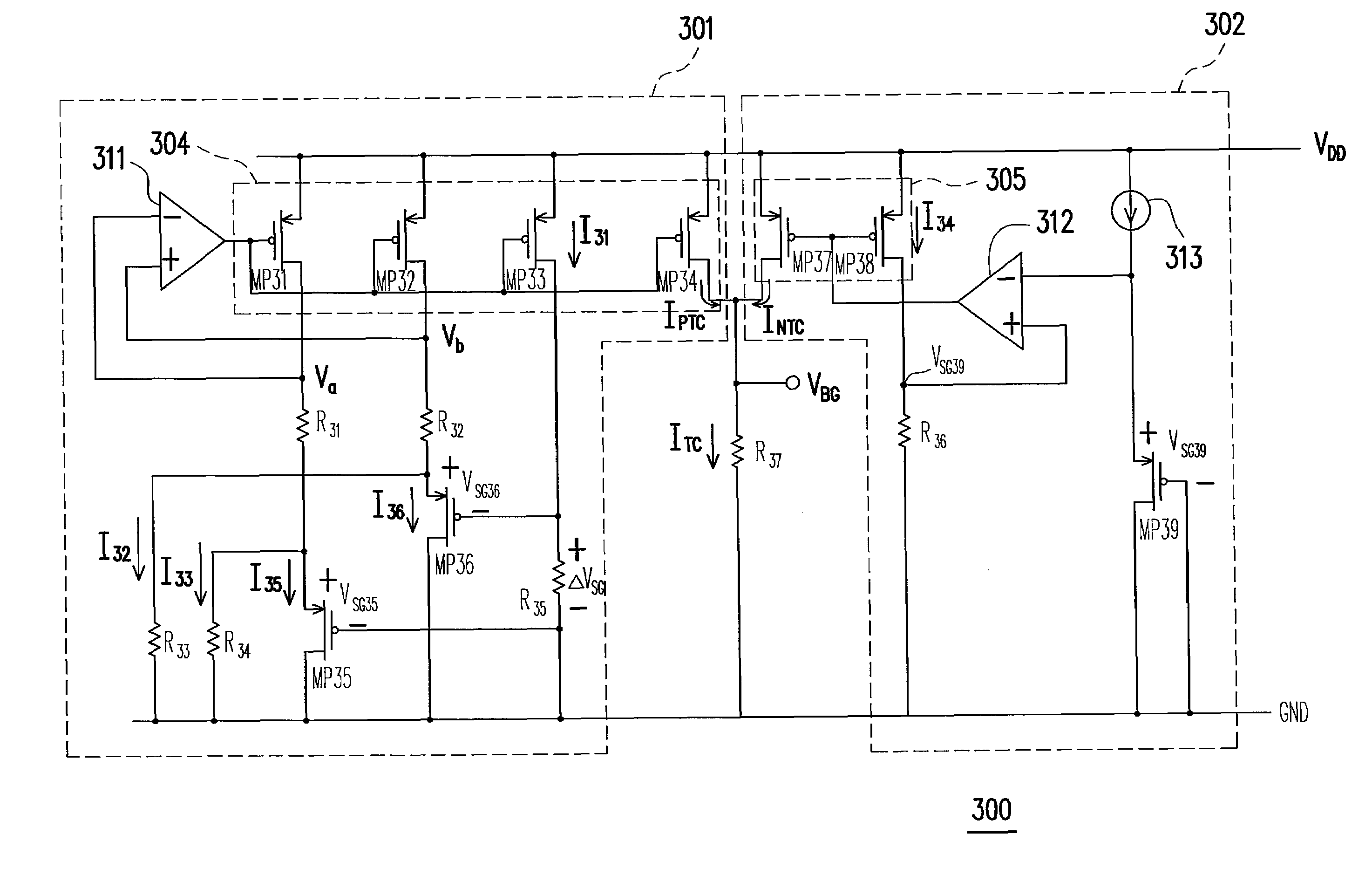
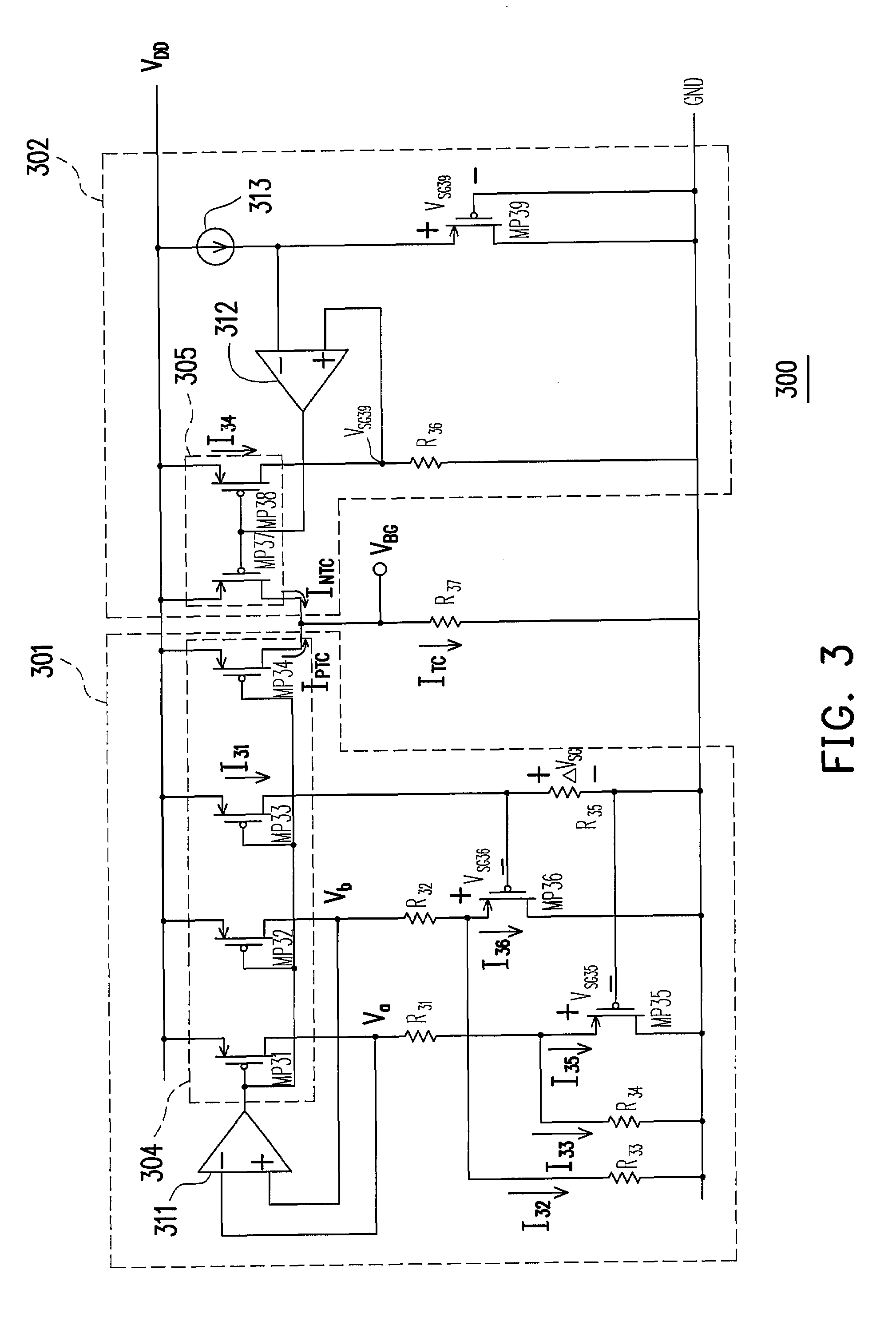
[0021]FIG. 3 shows a voltage reference circuit according to an embodiment of the present invention. The voltage reference circuit comprises a positive temperature coefficient current generator 301, a negative temperature coefficient current generator 302, and a resistor R37. The positive temperature coefficient generator 301 is used to generate a positive temperature coefficient current IPTC, and the negative temperature coefficient current generator 302 is used to generate a negative temperature coefficient current INTC. Then, two currents IPTC and INTC flow into R37 to form a temperature-independent current ITC. The current ITC flows through the resistor R37 to form a stable reference voltage VBG with low temperature dependence.

[0022]The positive temperature coefficient current generator 301 comprises an operation amplifier 311, a positive temperature coefficient current mirror 304 having PMOS transistors MP31˜MP34, PMOS transistors MP35, MP36, and resistors R31˜R34. Two input end...


PUM


Abstract

A voltage reference circuit including a positive temperature coefficient current generator, a negative temperature coefficient current generator, and a first resistor is provided. In the positive temperature coefficient current generator, two transistors are operated in the weak inversion region, and a second resistor is connected in series between the gates of the two transistors. The second resistor employs the characteristic that a transistor operated in weak inversion region acts like a bipolar junction transistor to generate a positive temperature coefficient current. The negative temperature coefficient current generator generates a negative temperature coefficient current in response to a negative temperature coefficient voltage drop on a third resistor. The positive temperature coefficient current and the negative temperature coefficient current flow through the first resistor together, thus producing a stable reference voltage.

Description

BACKGROUND OF THE INVENTION[0001]1. Field of Invention[0002]The present invention relates to a voltage reference circuit. More particularly, the present invention relates to a voltage reference circuit of a CMOS transistor.[0003]2. Description of Related Art[0004]FIG. 1 is a curve diagram of the relevant parameters of the semiconductor process technique. Supply voltage is scaling down because of reducing oxcide thickness. The threshold voltage (VTH) of MOS transistor, however, is not scale down as much as the supply voltage (VDD). Therefore, in the case that the voltage headroom is limited, all the analog circuits face the problem of maintaining their inherent capabilities under low operating voltage VDD.[0005]FIG. 2 is a circuit diagram of a conventional voltage reference circuit. The PMOS transistors MP21 and MP22 biased in the sub-threshold region are adopted to successfully obtain larger voltage headroom, such that the circuit can operate under lower operating voltage VDD. The c...

Claims


Application Information

Patent Timeline
IPC IPC(8): G05F3/16
CPCG05F3/262G05F3/30Y10S323/907
Inventor UANG, UEI-SHANCHANG, KUEN-SHANCHEN, MEI-SHOW
Owner FARADAY TECH CORP
Why Eureka
Try Eureka