Method and device for operating tank farm systems which are interconnected with pipes in a fixed manner and which have pipe systems for liquids

a tank farm and fixed connection technology, applied in the direction of liquid transfer devices, applications, liquid handling, etc., can solve the problems of yeast stopping its germicidal performance, restricting the exchange of substances, and unable to provide for an expulsion of products, so as to avoid product losses

Active Publication Date: 2007-12-04
GEA BREWERY SYST
View PDF13 Cites 12 Cited by
  • Summary
  • Abstract
  • Description
  • Claims
  • Application Information

AI Technical Summary

Benefits of technology

[0031]It is the object of the invention to provide a method for operating tank farm systems in a fixedly piped interconnection with piping systems for liquids, which poses high microbiological quality requirements and enables the device for its implementation to be configured easier than are comparable known devices.

Problems solved by technology

Problems will occur here when the setup and arrangement of piping between fermentation tanks and their peripheries, in an interaction with production flows, cause situations which create an environment that encourages the growth of germs.
Here, the drawback is that the tank volume in the respective tank 1.1 to 1.n inevitably is also the contents each of the tank discharge line 8.1.1* to 8.1.n* associated therewith and the traverse 9.1.1 to 9.1.n which joins it, and that this portion takes part in the treatment process (the fermentation process, in this embodiment) in the tank 1.1 to 1.n only to a very limited degree because of the geometry and arrangement conditions, which also results only in a restricted exchange of substance there.
However, the main problem encountered for the tank 1.1 to 1.n fixedly piped to the valve block VB, that cannot be disconnected in each case in its tank discharge line 8.1.1* to 8.1.n* leading to the valve block VB, substantially is that is it impossible to provide for an expulsion of the product P and a separate cleaning R1 of the tank discharge lines 8.1.1* to 8.1.n* and the associated traverses 9.1.1 to 9.1.n.
As a result, the yeast stops its germicidal performance.
The germs which thus multiply without any control and virtually cannot be reached are entrained into other tanks and production areas be-cause of the emptying, yeast extraction, and repumping operations that succeed, and will be a burden on the product.
However, such a measure mostly is worthwhile only for very long lines within the valve block VB.
In any case, the “counter-expulsion” or “pipe circuit expulsion” will necessitate a significant installation expenditure.
Such processes can lead to an undesirable growth of germs.Increases in temperature, e.g. as a result of hot cleaning operations, cause an environment in the traverses of the valve block that encourages an undesirable growth of germs.Specifically in horizontally disposed valve blocks and in case of long lines, the product P contained therein is not involved in the treatment process in the tank.
Thus, no exchange of substance or merely a low exchange will take place in the pipe line portions in question.Avoiding areas of a non-expelled product P in the classical valve matrixes discussed above, diminishing losses of product, and allowing those areas to be separately cleaned even if the tank is full requires a very large expenditure in the periphery of the valve matrix that cannot be realized in most cases for reasons of economy and leads to difficult-to-survey piping systems which necessitate a lot of maintenance.
For these reasons, when the problems are tackled in practice, compromising solutions are found that exhibit more or less pronounced restrictions.The air which has entered the tank discharge line and the discharge line joining it in conjunction with the traverse during tank cleaning prevents the piping system from being properly cleaned.

Method used


Image

  • Method and device for operating tank farm systems which are interconnected with pipes in a fixed manner and which have pipe systems for liquids
  • Method and device for operating tank farm systems which are interconnected with pipes in a fixed manner and which have pipe systems for liquids
  • Method and device for operating tank farm systems which are interconnected with pipes in a fixed manner and which have pipe systems for liquids

Examples


Embodiment Construction

[0056]While this invention maybe embodied in many different forms, there are described in detail herein a specific preferred embodiment of the invention. This description is an exemplification of the principles of the invention and is not intended to limit the invention to the particular embodiment illustrated

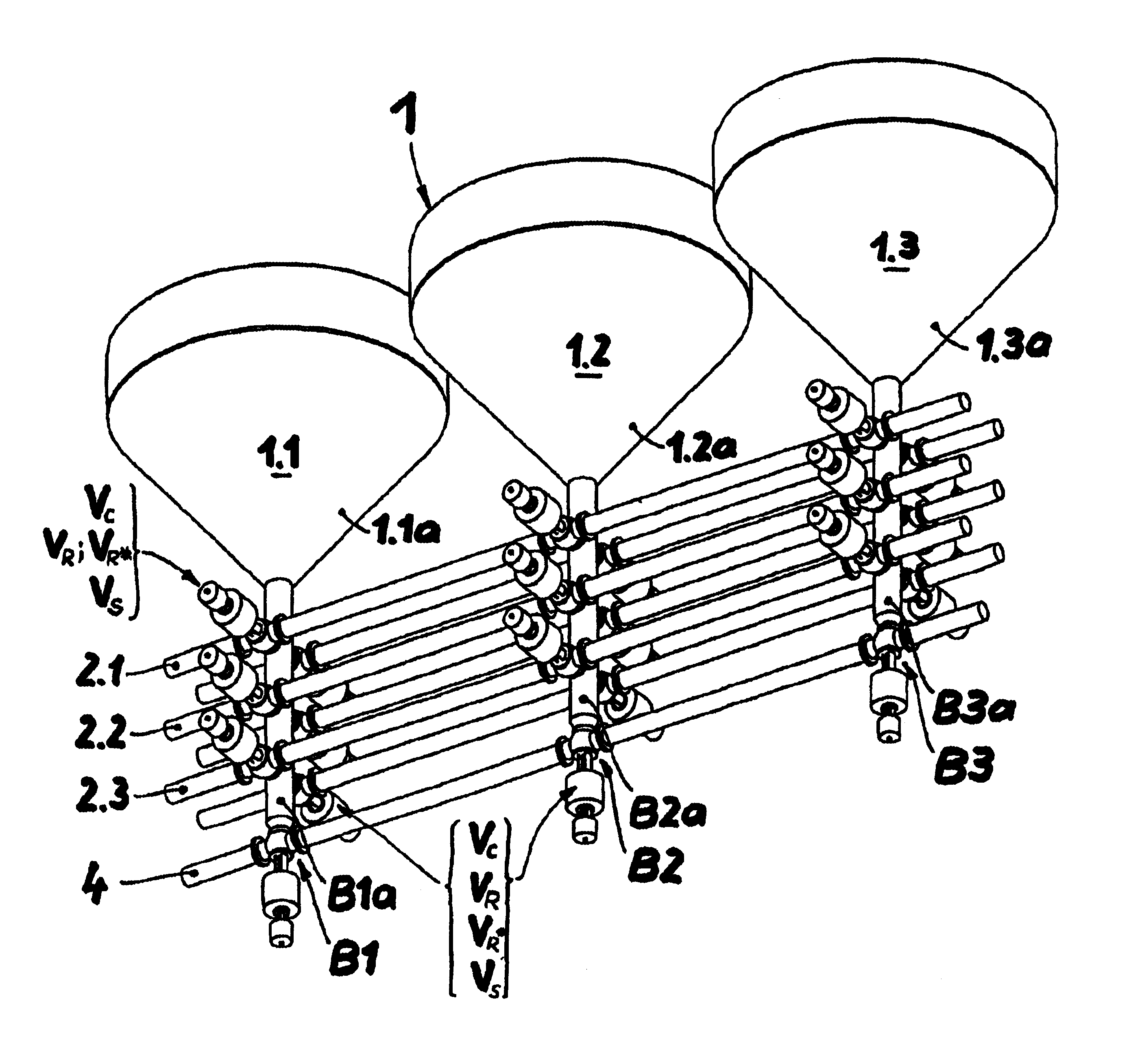
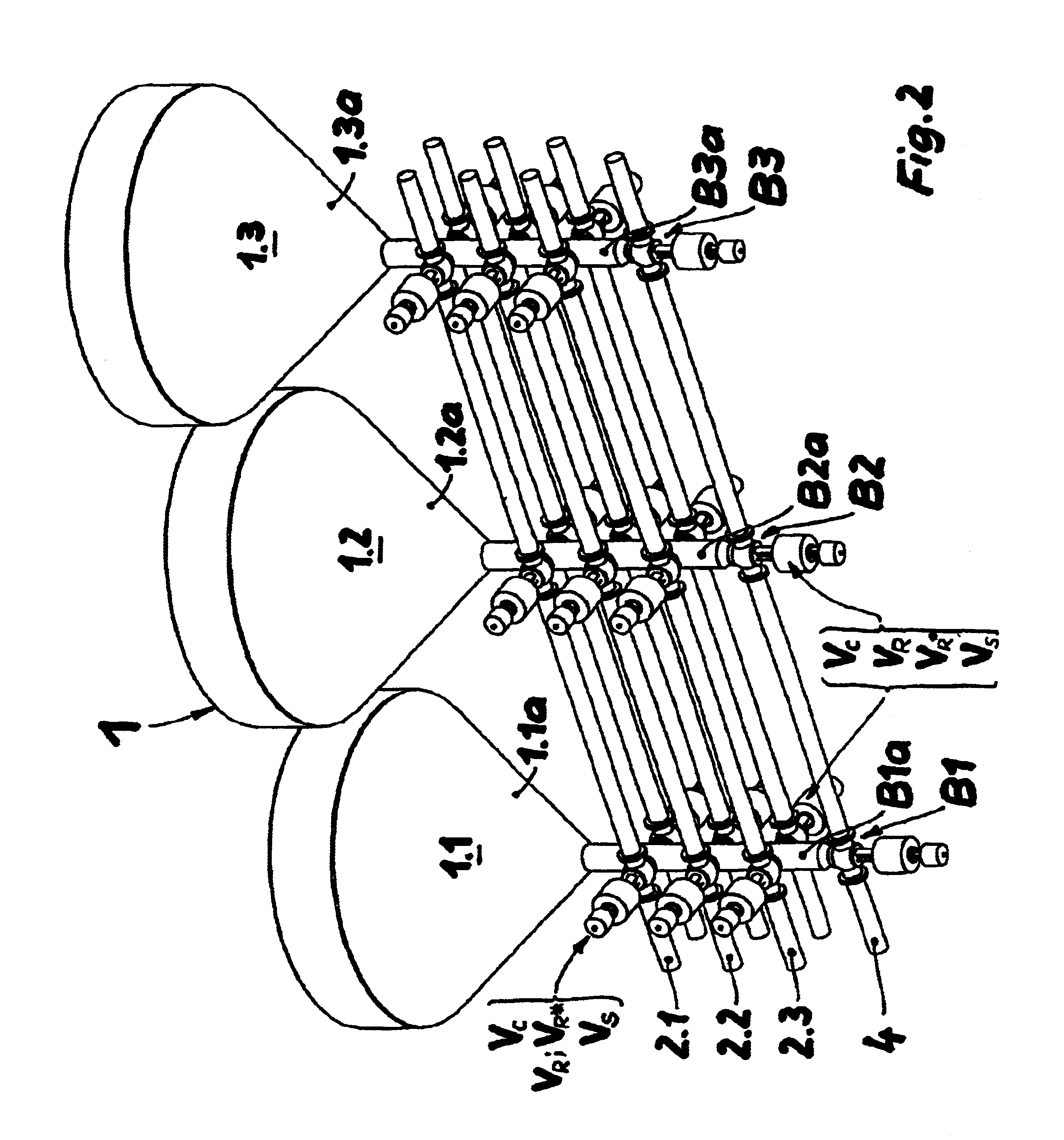
[0057]FIG. 2 shows a tank farm system 1 which comprises three tanks 1.1, 1.2, and 1.3 in a row-shaped array. Each tank bottom 1.1a, 1.2a, 1.3a of each respective tank 1.1, 1.2, 1.3, at its lower end, opens out into a valve manifold tree B1, B2, B3 which is preferably formed as an elongate hollow body B1a, B2a, B3a in the form of a cylindrical tube. The longitudinal axis of the hollow body B1a, B2a, B3a is oriented perpendicularly and coaxially with the longitudinal axis of the respective tank 1.1 to 1.3. The lowermost end of the respective hollow body B1a to B3a that faces away from the tank bottom 1.1a to 1.3a has disposed thereon a cleaning pipe line 4 which continuously join...


PUM

PropertyMeasurementUnit
angleaaaaaaaaaa
areaaaaaaaaaaa
circumferenceaaaaaaaaaa

Abstract

The invention relates to a method for operating tank farm systems, which are interconnected with pipes in a fixed manner and which have pipe systems for liquids, particularly for use in systems which are subject to high microbiological quality requirements and which are used for processing and transferring products in the foodstuffs and beverage industry, pharmaceutical industry, and biotech industry. The invention provides that the supply and discharge of liquids into and out of the respective tank ensues from underneath, and that the liquids that are being supplied or discharged flow through a space which is directly connected to the respective tank contents and which is situated underneath the respective tank in a switchable manner, and in a manner that ensures mixing, from the pipes of the pipe system that lead to this space.

Description

CROSS-REFERENCE TO RELATED APPLICATIONS[0001]Not ApplicableSTATEMENT REGARDING FEDERALLY SPONSORED RESEARCH[0002]Not ApplicableBACKGROUND OF THE INVENTION[0003]The invention relates to a method and device for operating tank farm systems in a fixedly piped interconnection with piping systems for liquids, particularly for use in plants subjected to high microbiological quality requirements for product treatment and for product transfer in the foodstuff and beverage industries, pharmacy, and biotechnology.[0004]The microbiological requirements which are made nowadays to production plants in the field of the foodstuff and beverage industries, pharmacy, and biotechnology grow to the extent at which measuring procedures to establish microbiological loads are improved and the limits of detectability are reduced for substances of any types. As a typical example, which is also vicarious for other applications, the document quotes fermentation processes below (e.g. the fermentation sector in ...

Claims


Application Information

Patent Timeline
Patent Type & Authority Patents(United States)
IPC IPC(8): F17D1/00F17D1/08B67C3/22B67D7/78C12C1/00C12C13/00
CPCC12C11/006Y10T137/0318Y10T137/5762Y10T137/4857Y10T137/4673
Inventor WORCZINSKI, GUNTER
Owner GEA BREWERY SYST
Why Eureka
Try Eureka