Vacuum pill dispensing cassette and counting machine

a technology for dispensing cassettes and vacuum pills, which is applied in the direction of instruments, packaging goods types, de-stacking articles, etc., can solve the problems of increasing the motor speed, reducing the required vacuum source, and not allowing the pill released from the pickup tube to fall under gravity into the discharge tube, etc., to reduce the audible noise levels, reduce the turbulence of airflow, and reduce the effect of requirements

Active Publication Date: 2007-12-04
MCKESSON AUTOMATION SYST
View PDF45 Cites 27 Cited by
  • Summary
  • Abstract
  • Description
  • Claims
  • Application Information

AI Technical Summary

Benefits of technology

[0012]The present invention overcomes the problems outlined above and provides a pill storage and dispensing cassette for storing and dispensing pills (e.g., tablets, capsules, caplets, gel-caps, or pills) or similarly shaped articles from a bulk storage chamber and regulates the pill flow into a pick-up area so as to maintain a preferred amount of pills in the pick-up area without crushing or damaging the pills. The vacuum source is not in communication with the openings in the rotatable conveying wheel while the openings are rotated within the discharge chute of the cassette. By eliminating the airflow through those openings, the vacuum source requirements are reduced. The venturi design of the plurality of openings in the rotatable conveying wheel maintains an equivalent airflow and vacuum pressure differential through the openings in the conveying wheel but reduces the airflow turbulence and substantially reduces the audible noise levels. As a result of those features, and others, the present invention enables a reduction in the size of the vacuum motor of the counter, which in turn results in reduced air turbulence and quieter operation.

Problems solved by technology

Adjustment of the vacuum shut off for each type of pill requires the operator to spend a considerable amount of time before dispensing a new pill type for a patient prescription.
Another limitation of the '302 patent is that it relies on inertia to ‘throw’ the pill from the pickup tube into the discharge chute when the vacuum is released; the design does not appear to allow a pill released from the pickup tube to fall under gravity into the discharge tube.
Another limitation is the ends of the pick up tubes are modified to accommodate different pill shapes and may include the application of an adhesive to promote the adherence of pills to the pick up tube.
Increasing the motor speed is unlikely to improve the performance due to the reduced efficiency of the pickup tubes at higher speeds and the likelihood of the pickup tubes damaging or breaking the pills in the hopper.

Method used


Image

  • Vacuum pill dispensing cassette and counting machine
  • Vacuum pill dispensing cassette and counting machine
  • Vacuum pill dispensing cassette and counting machine

Examples


Embodiment Construction

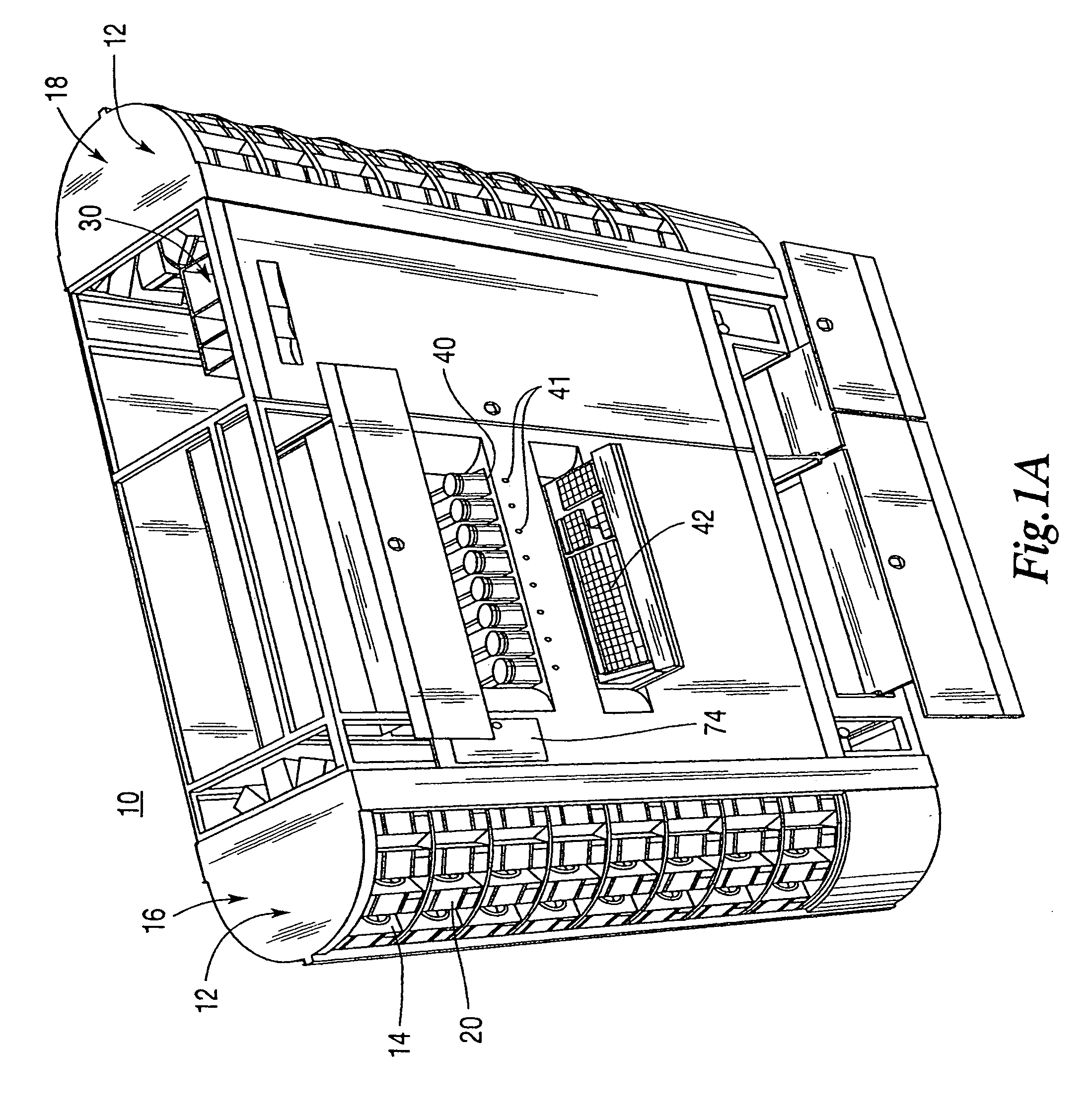
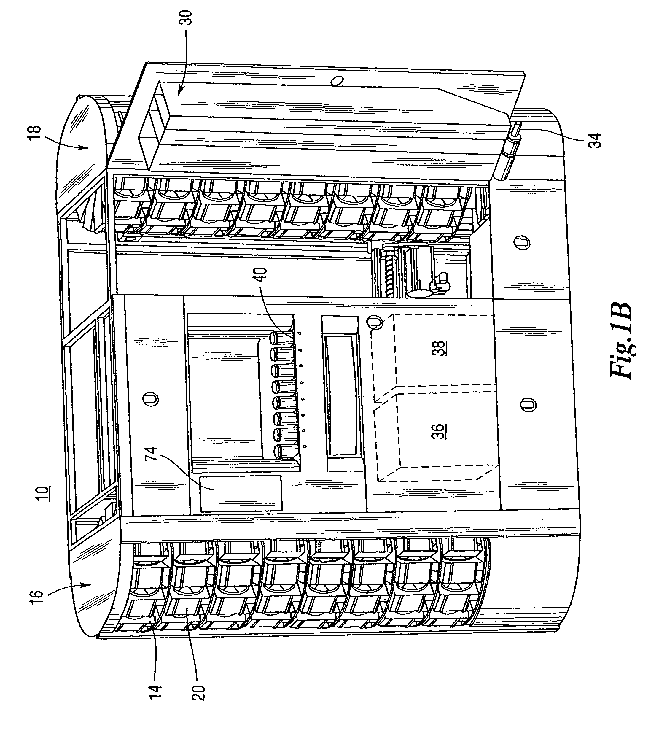
[0046]FIGS. 1A and 1B are two perspective views, taken from the front, with various doors and drawers opened, of one embodiment of a prescription filling apparatus 10 of the present invention. The apparatus 10 technically fills vials, which are normally for a prescription, but need not be, such that reference to apparatus 10 as a prescription filling apparatus is not intended to limit its use or the scope of the claims to filling prescriptions. FIG. 1C is a top view of the apparatus 10. FIG. 2 shows a perspective view of the prescription filling apparatus 10 of the present invention taken from the rear. All references to front, back, left and right are taken with respect to the orientation shown in FIG. 1A.

[0047]In FIGS. 1A, 1B, 1C and 2, apparatus 10 includes at least one shelving unit 12 which includes an array of storage locations 14. In FIGS. 1A, 1B, 1C and 2 a pair of shelving units 12 is implemented as a pair of carousels, a left carousel 16 and a right carousel 18. However, s...


PUM


Abstract

A medication storing and dispensing cassette is comprised of a housing defining at least a portion of a bulk storage chamber for storing a medication, defining at least a portion of a pick-up area, and defining at least a portion of a discharge chute sized to temporarily store a quantity of the medication. A divider wall is positioned between the bulk storage chamber and the pick-up area. A gate is positioned to control an exit end of the discharge chute. A rotatable conveying wheel having openings proximate to the periphery thereof is positioned such that a portion of the wheel is in communication with the pick-up area while another portion of the wheel is adjacent to an entrance end of the discharge chute. A calibration arm is positioned adjacent the openings of the rotatable wheel. A baffle is positioned to block those openings in that portion of the rotatable wheel adjacent to the discharge chute. An air agitation system is provided so that pills may be moved from the bulk storage chamber to the pick-up area. Methods are also disclosed in which air agitation is used to move pills from the bulk storage chamber to the pick-up area, for automatically setting the position of the calibration arm and for automatically learning the setting for the calibration arm for an unclassified medication. A counter is also disclosed for use with the cassette. The counter is comprised of a loader for receiving a cassette, a sensor for sensing whether a cassette is in the loader, means for moving the loader into an operative position, a vacuum unit for applying a vacuum to the cassette, a drive unit for driving a driven portion of the cassette and a counter for counting medication within a portion of the cassette. Methods of operating the counter are also disclosed.

Description

CROSS REFERENCE TO RELATED APPLICATIONS[0001]This application claims the benefit of U.S. Provisional Application No. 60 / 402,485 filed Aug. 9, 2002 and entitled Prescription Filling Apparatus Implementing A Pick And Place Method, the entirety of which is hereby incorporated by reference. This application is related to U.S. application Ser. No. 10 / 423,579 filed herewith and entitled Prescription Filling Apparatus Implementing A Pick and Place Method.BACKGROUND OF THE INVENTION[0002]1. Field of the Invention[0003]The present invention is broadly concerned with pill dispensing devices as well as with storage and dispensing cassettes useful in automated dispensing equipment and especially for use in pill dispensing devices.[0004]2. Description of the Background[0005]U.S. Pat. No. 4,018,358 covers the Drug-O-Matic (DOM) cassette and counting machine available from McKesson Automation Systems Inc. of Pineville, La. The original DOM cassette relied upon a pill separator positioned to separa...

Claims


Application Information

Patent Timeline
Patent Type & Authority Patents(United States)
IPC IPC(8): B65H1/00A61J7/00A61J7/02B65B1/30B65B5/10B65B57/20G07F11/44G07F11/54G07F11/58G07F11/62G07F11/64
CPCB65B5/103B65B57/20G07F11/44G07F17/0092G07F11/58G07F11/62G07F11/64G07F11/54G07F11/1657
Inventor HUTCHINSON, KEVINSELF, ANTHONYINABNET, JOSEPHMILTON, MONROEBERGERON, MIKE
Owner MCKESSON AUTOMATION SYST
Why Eureka
Try Eureka