
Methods of forming integrated circuit devices including a multi-layer poly film cell pad contact hole

Inactive Publication Date: 2007-12-11
SAMSUNG ELECTRONICS CO LTD
View PDF10 Cites 2 Cited by
  • Summary
  • Abstract
  • Description
  • Claims
  • Application Information

AI Technical Summary

Problems solved by technology

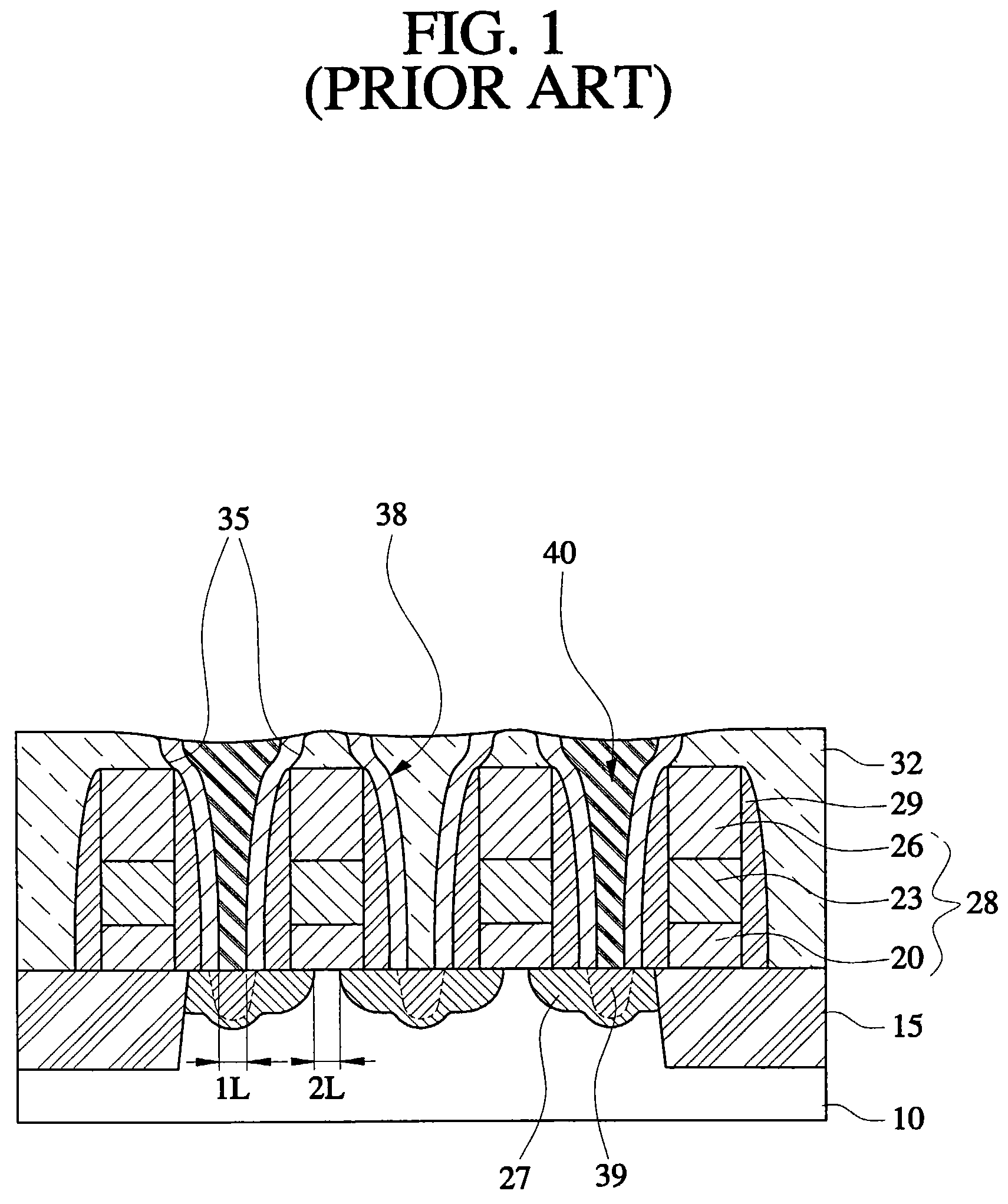
Two kinds of known failures in such devices result from an increase and a decrease in the resistance of the cell pad contact hole detected, for example, during Electrical Die Sorting (EDS) testing of the integrated circuit device.
The integrated circuit device may then have a refresh failure as a result of a reduction of a sensing margin of the device from the voltage drop of the cell pad contact hole.
The resulting cell pad contact hole may exhibit a very low resistance.
As a result, the high voltage level of data transmitted from the peripheral circuit region through the cell pad contact hole may affect (leak into) an adjacent channel region under a gate of the integrated circuit device because the region between the cell pad contact and the gate may be insufficient given the size of the cell pad contact region.
The integrated circuit device may then have a refresh failure as a result of a reduction of sensing margin caused by the voltage leak.
However, the effective channel length of a gate adjacent to the cell pad contact hole may be reduced because ions and / or dopants from the two processes may be diffused into the semiconductor substrate, which may cause a dynamic refresh fail in the semiconductor device.
As a result, the semiconductor device structure may result in poor refresh operation and deteriorate a performance characteristic of the semiconductor device.

Method used


Image

  • Methods of forming integrated circuit devices including a multi-layer poly film cell pad contact hole
  • Methods of forming integrated circuit devices including a multi-layer poly film cell pad contact hole
  • Methods of forming integrated circuit devices including a multi-layer poly film cell pad contact hole

Examples


Embodiment Construction

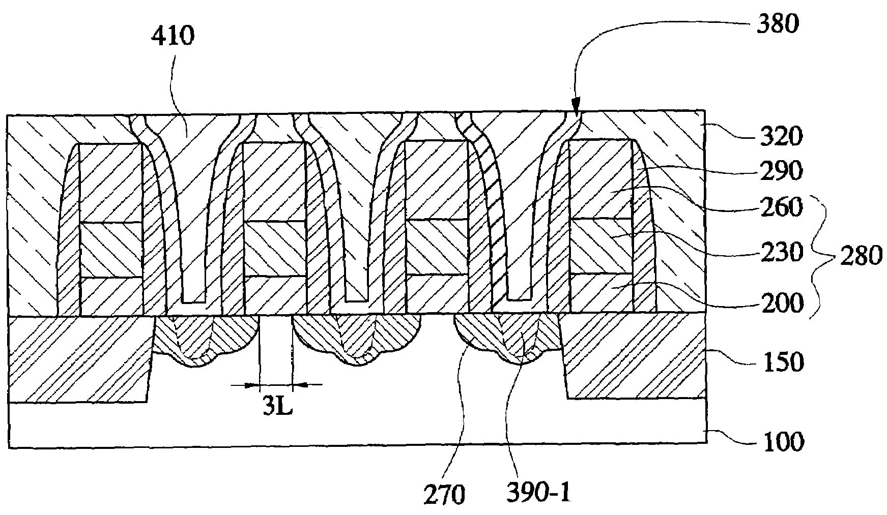
[0026]The present invention now will be described more fully hereinafter with reference to the accompanying drawings, in which preferred embodiments of the invention are shown. This invention may, however, be embodied in many different forms and should not be construed as limited to the embodiments set forth herein; rather, these embodiments are provided so that this disclosure will be thorough and complete, and will fully convey the scope of the invention to those skilled in the art. Like numbers refer to like elements throughout. It will be understood that when an element is referred to as being “on” or “connected to” or “coupled to” another element, it can be directly on, connected to or coupled to the other element or intervening layers or elements may also be present. In contrast, when an element is referred to as being “directly on” or “directly connected to” or “directly coupled to” another element, there are no intervening layers or elements present. The relative thickness o...


PUM


Abstract

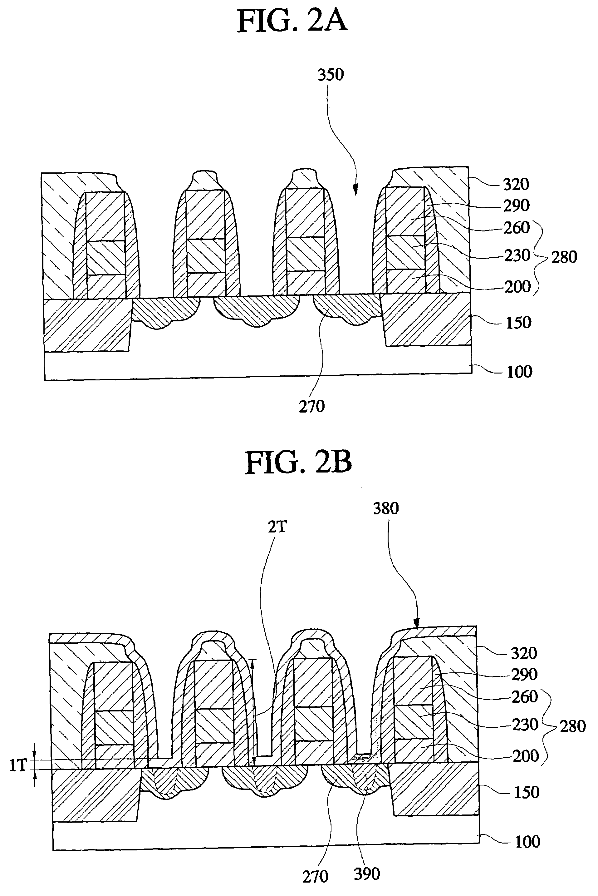
Methods of forming a cell pad contact hole on an integrated circuit include forming adjacent gates on an integrated circuit substrate having a source / drain region extending between the gates. Gate spacers are formed on facing sidewalls of the adjacent gates. A cell pad contact hole is formed aligned to the gates and gate spacers that exposes the source / drain region in the integrated circuit substrate. A first poly film is formed in the cell pad contact hole. An ion region is formed in the source / drain region by ion-implanting through the first poly film and a second poly film is formed on the first poly film that substantially fills the cell pad contact hole.

Description

RELATED APPLICATION[0001]This application claims priority to Korean Patent Application 2002-49548, filed on Aug. 21, 2002, the contents of which are herein incorporated by reference in their entirety.BACKGROUND OF THE INVENTION[0002]The present invention relates to integrated circuit devices, and more particularly, to integrated circuit devices including a cell pad contact hole and methods for forming the same.[0003]Integrated circuit (semiconductor) devices are widely used in consumer and commercial applications. Such devices may include cell pad contact holes. Two kinds of known failures in such devices result from an increase and a decrease in the resistance of the cell pad contact hole detected, for example, during Electrical Die Sorting (EDS) testing of the integrated circuit device.[0004]In some cases, a cell pad contact hole may be formed that is smaller than the size specified by a design rule for the integrated circuit device's manufacturing process. As a result, the cell p...

Claims


Application Information

Patent Timeline
IPC IPC(8): H01L21/425H01L27/108H01L21/336H01L21/60H01L21/768
CPCH01L21/76897H01L21/76895H10B12/00
Inventor OH, YONG-CHULJIN, GYO-YOUNG
Owner SAMSUNG ELECTRONICS CO LTD
Learn More