Method of detecting mask defects, a computer program and reference substrate

Active Publication Date: 2007-12-11
ASML NETHERLANDS BV
View PDF22 Cites 2 Cited by
  • Summary
  • Abstract
  • Description
  • Claims
  • Application Information

AI Technical Summary

Benefits of technology

[0015]It is, therefore, an aspect of the present invention to provi

Problems solved by technology

Defects in the mask, or mask pattern can result in defective devices, such as ICs, and are therefore undesirable.
Firstly, contamination, such as dirt or stains, on a transparent or reflective part of the mask can block and/or distort exposing radiation and print onto the substrate as though it were a part of the pattern.
Secondly, cracks in the mask material (e.g. quartz) can block or scatter radiation, therefore cau

Method used


Image

  • Method of detecting mask defects, a computer program and reference substrate
  • Method of detecting mask defects, a computer program and reference substrate
  • Method of detecting mask defects, a computer program and reference substrate

Examples


Example

[0036]In the Figures, corresponding reference symbols indicate corresponding parts.

DETAILED DESCRIPTION

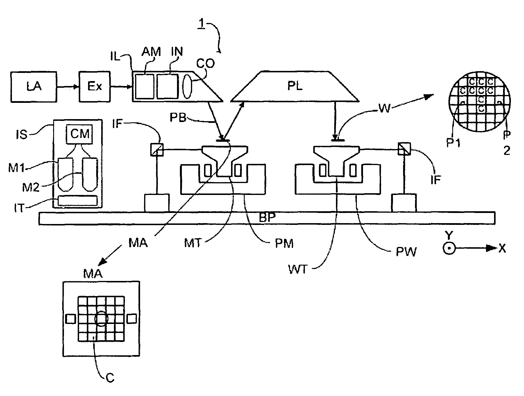
[0037]FIG. 1 schematically depicts a lithographic projection apparatus which is used in at least one embodiment. The apparatus includes[0038]a radiation system Ex, IL, for supplying a projection beam PB of radiation (e.g. EUV radiation), which in this particular case also comprises a radiation source LA;[0039]a first object table (mask table) MT provided with a mask holder for holding a mask MA (e.g. a reticle), and connected to first positioning means for accurately positioning the mask with respect to item PL;[0040]a second object table (substrate table) WT provided with a substrate holder for holding a substrate W (e.g. a resist-coated silicon wafer), and connected to second positioning means for accurately positioning the substrate with respect to item PL;[0041]a projection system (“lens”) PL (e.g. a refractive lens system group) for imaging an irradiated portion of the mask MA...


PUM


Abstract

A method of detecting mask defects in which a reference substrate is patterned by the mask immediately after manufacture of the mask is disclosed. The reference substrate is stored in clean conditions while IC manufacture takes place. When a mask defect is suspected, a resist coated substrate, the test substrate, is patterned by exposure of the mask. The patterns on the reference substrate and the test substrate are compared to determine if there is a mask defect. The location of the mask defect can be found by scanning smaller areas of the patterns.

Description

CROSS-REFERENCE TO RELATED APPLICATIONS[0001]This application is based on and claims priority from European Patent Application No. 02257465.1 filed on Oct. 28, 2002, the contents of which are incorporated herein by reference.BACKGROUND[0002]1. Field[0003]The present invention relates generally to the field of lithography. More specifically, the present invention relates to a method of detecting errors in patterning devices used in photolithographic apparatus.[0004]2. Description of Related Art[0005]The term “patterning device” as here employed should be broadly interpreted as referring to means that can be used to endow an incoming radiation beam with a patterned cross-section, corresponding to a pattern that is to be created in a target portion of the substrate; the term “light valve” can also be used in this context. Generally, the said pattern will correspond to a particular functional layer in a device being created in the target portion, such as an integrated circuit or other d...

Claims


Application Information

Patent Timeline
IPC IPC(8): G01N21/00G01B11/24G01B11/00G01N21/956G03F1/08G03F1/16G03F7/20H01L21/027H01L21/66
CPCG03F7/7065H01L21/027
Inventor VAN DER WERF, JAN EVERTMUD, AUKE JAN
Owner ASML NETHERLANDS BV
Why Eureka
Try Eureka