Heat sink assembly with overmolded carbon matrix

Inactive Publication Date: 2007-12-25
TICONA POLYMERS INC
View PDF70 Cites 28 Cited by
  • Summary
  • Abstract
  • Description
  • Claims
  • Application Information

AI Technical Summary

Benefits of technology

[0012]The present invention preserves the advantages of prior art heat dissipation devices, heat sinks and heat spreaders. In addition,

Problems solved by technology

For example, a PENTIUM microprocessor, containing millions of transistors, is highly susceptible to overheating which could destroy the microprocessor device itself or other components proximal to the microprocessor.
However, these external devices consume power and have numerous moving parts.
As a result, heat sink assemblies with active devices are subject to failure and are much less reliable than a device which is solely passive in nature.
For example, video cards, which are capable of processing millions of polygons per second, are also susceptible to overheating and need efficient and effective cooling as do the CPUs discussed above.
Since the machining process is limited, the geometry of the fin configuration of a machined he

Method used


Image

  • Heat sink assembly with overmolded carbon matrix
  • Heat sink assembly with overmolded carbon matrix

Examples


Embodiment Construction

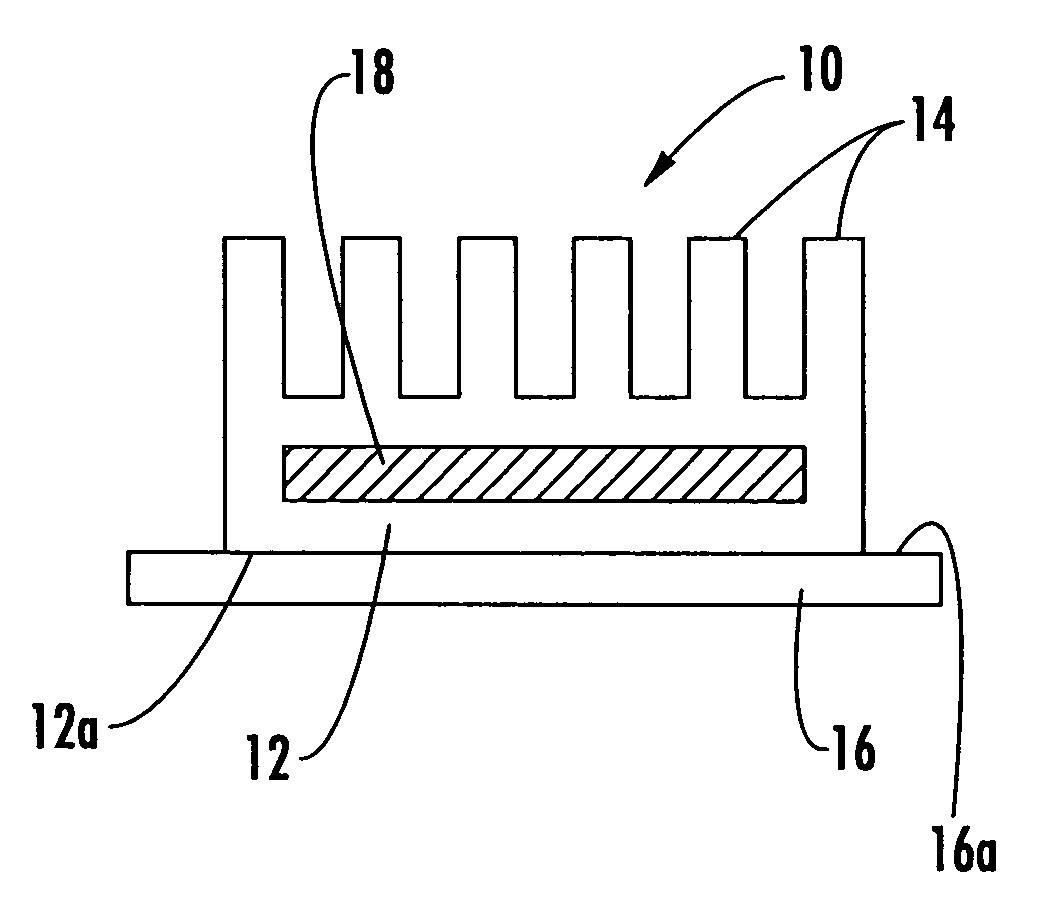
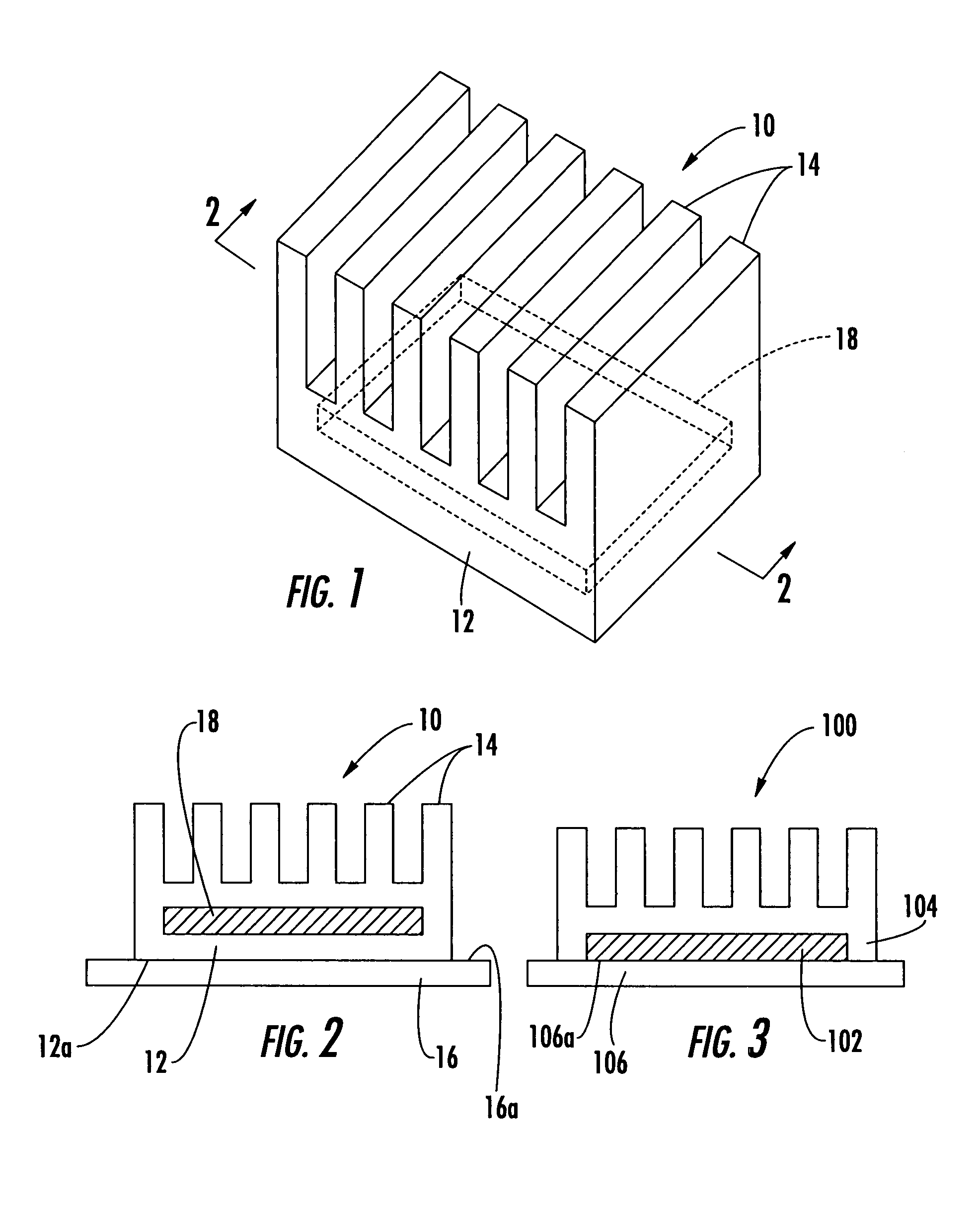
[0023]Referring first to FIGS. 1-3, the net-shape molded heat sink 10 of the present invention is shown. In FIG. 1, a perspective view of the molded heat sink 10 of the present invention is shown while FIG. 2 illustrates a cross-sectional view through the line 2-2 of FIG. 1. The molded heat sink 10 includes a main body section 12 with a number of upwardly extending heat dissipating members 14. The molded heat sink 10 is net-shape molded, such as by injection molding, into a unitary structure from thermally conductive material, such as a thermally conductive polymer composition. The thermally conductive polymer composition includes a base polymer of, for example, a liquid crystal polymer that is loaded with a conductive filler material, such as copper flakes or carbon fiber. Other base materials and conductive fillers may be used and still be within the scope of the present invention. For example, other fillers that may be employed include copper, aluminum, carbon, magnesium and boro...


PUM

PropertyMeasurementUnit
Electrical conductoraaaaaaaaaa
Configurationaaaaaaaaaa

Abstract

A net-shape molded heat sink is provided which includes a thermally conductive main body and a number of thermally conductive fins integrally connected to and emanating from the main body. The heat sink is formed by overmolding a carbon-carbon matrix core plate with a thermally conductive polymer composition that is filled with thermally conductive filler material. The molded heat sink is freely connecting through the part which makes it more efficient and has an optimal thermal configuration.

Description

CROSS-REFERENCE TO RELATED APPLICATIONS[0001]This application is related to and claims priority from earlier filed provisional patent application No. 60 / 178,949, filed Feb. 1, 2000 and is a divisional of earlier filed patent application Ser. No. 09 / 774,521, filed Jan. 31, 2001 now U.S. Pat. No. 6,680,015.BACKGROUND OF THE INVENTION[0002]The present invention relates generally to the cooling of heat generating surfaces and objects. More specifically, the present invention relates to apparatuses for dissipating heat generated by such objects. In addition, the present invention relates to cooling of heat generating objects by use of composite materials and devices without the use of external fans to assist in cooling.[0003]In industry, there are various parts and components that generate heat during operation. For example, in the electronics and computer industries, it is well known that computer components generate heat during operation. Various types of electronic device packages and...

Claims


Application Information

Patent Timeline
IPC IPC(8): H05K7/20H01L21/48H01L23/373
CPCH01L21/4871H01L23/373Y10T428/30H01L2924/0002H01L2924/00Y10T428/31678
Inventor MCCULLOUGH, KEVIN A.
Owner TICONA POLYMERS INC
Why Eureka
Try Eureka